Oboe Navigation
(Nov 1942-May 1945)
There is no need for any form of display in the air, all signals received by the pilot and navigator being aural. The equipment carried in the aircraft consists of a receiver which is used to trigger the pulse repeater transmitter.
A double filter is also required to separate signals from the two ground stations, CAT and MOUSE and to convert the pulse intelligence received into audible indications for the aircrew
The early gear was known as the Pea-cock equipment (ARI.5513) and worked on the 1 metre band.
For centimetre working Album Leaf equipment is used (ARI.5582) and worked on the 10 cm band. This used an American ASG type transmitter. Album Leaf is now termed Oboe Mk. II.
.
Introduction to Oboe Navigation
Oboe is a system of blind-bombing where an aircraft is controlled by two ground stations. Each of these stations uses the normal radar technique to measure the range of the aircraft from it, therefore, at any time the position of the aircraft can be found by the range-cut principle. The code name Oboe covers airborne equipment and the ground stations are called AMES type 9000; the AMES acronym became the basis for naming RAF radar systems throughout the war.
A pulse repeater is carried in the aircraft, to increase the range of the device above that of RADAR waves alone being used. Therefore, there is a two-way transmission and without multiple equipment, two stations will only be able to control one aircraft at a time.
The inaccuracy of our all-weather bombing, especially at night, had been recognised for some time; something had to be done. In 1942, a blind-bombing device was developed called Oboe, this was controlled by two English ground stations, separated by 200 miles, that communicated individually the current location to an R.A.F Path Finder aircraft using radar pulses. Oboe was the brainchild of Alec Reeves, the PCM (pulse code modulation) wizard of Standard Telephones and Cables Ltd, who along with Frank Jones, were stationed at TRE Worth 1. The basic principle of Oboe is simple. The range of a target, say the Krupps armament works in Essen, measured from two widely spaced ground stations in the UK, was derived from pre-war ordnance survey maps and aerial photographs.
Oboe was first used operationally in the early part of 1943. The Mk. I equipment was used at that time, but since then other Marks have been developed. These will all be described later. There are, however, certain fundamental facts common to all of them, and these will be dealt with first
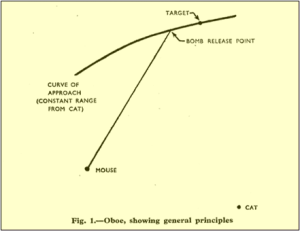
One ground station, code-named CAT, controlled the track of the marker aircraft, usually a Mosquito, by interrogating an on-board transponder located on the aircraft. At the groundstation, the returned pulse was displayed on a cathode ray tube with a delayed, magnified time-base. The precise range of the target from the CAT station was set up on the display tube by a strobe marker.
The Mosquito flew on a circular arc centred on this station at a radius equal to the target range, appearing stationary on the tube face located at CAT station, i.e. zero radial velocity. The purpose of the CAT was to keep the returned pulse exactly in line with the target marker strobe by automatically signalling dots or dashes to the Mosquito; dots if the Mosquito range was less than the target range, dashes if it was greater. The dots and dashes merged into a continuous note when the Mosquito range was correct.
The sensitivity of the system was such that a deviation of plus or minus 16 metres from the circular arc would cause either dots or dashes to be sent, thereby enabling the pilot to steer along an invisible track some 32 metres wide in the sky above the target.
The other ground station, code-named MOUSE, signalled the Mosquito as it passed a number of ‘milestones’ or countdown time to target along the arc until it reached the release point – the intersection of the Cat and Mouse ranges when the bomb release signal (five dots and a dash) was given automatically. Like the Cat station, the target was set by a strobe on a CRT with a delayed, magnified time base. Unlike the Cat, the returned pulse moved along the trace as the Mosquito approached the target region.
The precise release point was influenced by many factors e.g. time of bomb fall, trail distance, a function of bomb ballistics and airspeed, meteorological data, the velocity and heading of the Mosquito just prior to release plus instrumental corrections. These were taken into account by the ground station Mouse computer, the release point being continuously and automatically corrected to ensure that the predicted impact point of the bomb (or Target Indicator) was within the target zone.
There were several Oboe stations around the east and south coasts of England: Sennen Cove and Treen, Landsend Cornwall; Swanage, Dorset; Deal x2, Kent; Winterton and Trimmingham, Norfolk and Cleadon Durham.any of which could be nominated to perform a Cat or Mouse function depending on the target location.
The first MkI stations became operational by Bomber Command in late 1942 used modified Chain Home Low (CHL) equipment working on 200 MHz using pulse space modulation for signalling.
This was superseded in early 1944 by the Mk2 working on 3Ghz or 10 centimetres. The Swanage station, operational name Tilly Whim, was manned by TRE Pilot Officers from TRE Worth
The first MkI stations became operational by Bomber Command in late 1942 used modified Chain Home Low (CHL) equipment working on 200 MHz using pulse space modulation for signalling.
This was superseded in early 1944 by the Mk2 working on 3Ghz or 10 centimetres. The Swanage station, operational name Tilly Whim, was manned by TRE Pilot Officers from TRE Worth.
Ground stations (AMES, type 9000)
The following text covers the topic in more depth and provides graphical examples to aid retention.
The two ground stations previously mentioned have different functions in an Oboe operation. One station keeps the aircraft flying along a track which will take it over the target (fig. 1). In general, the track along which the aircraft is made to fly is a circle drawn about the ground station as centre with a radius equal to the target range from that station, but it is possible to have arcs of approach to the target other than circular ones. In all cases, this station is known as the CAT or the tracker station, the latter being the more modern name.
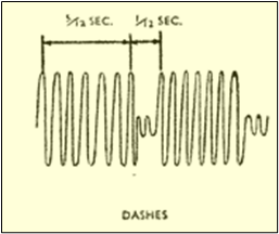
The tracker station measures the range of the aircraft and determine the latter is on its correct track. Indications of error in track are sent out from the tracker to the aircraft in such a manner that the pilot hears a series of dashes in a pair of headphones if he is too far from ground station, or a series of dots if he is too close. If he is on the correct track the pilot hears a continuous note in his headphones. All such indications to the pilot are sent out automatically from the tracker station by a modulating signal using the same pulse transmission frequency used for range measurement.
The function of the second ground station, is to send out to the aircraft navigator or bomb-aimer the bomb-release signals and warning signals are necessary. This station is known as the MOUSE. It measures the range of the aircraft and so also can obtain the velocity of the aircraft along a radius drawn towards it. Having this information, the height of the aircraft and bomb ballistic data, the MOUSE can send the release warning so that the bombs fall on the target. Usually, the release signal is sent by completely breaking the transmission from the Mouse 3.
Aircraft equipment
There is no need for any form of display in the air, all signals received by the pilot and navigator being aural. The equipment carried in the aircraft consists of a receiver which is used to trigger the pulse repeater transmitter. A double filter is also required to separate signals from the two ground stations and to convert the pulse intelligence received into audible indications for the aircrew, who wear headphones.
Operational technique
On large scale raids, the Oboe equipped aircraft act as pathfinders for the main force by dropping marker flares on to the target. On small scale raids on specialised targets the Oboe aircraft carry a bomb-load. Both Cat and Mouse stations can communicate with the aircraft in morse code over the radar pulsed beam. This is used for the preliminary positioning of the aircraft before it starts its run-in. The range achieved is of the order of 250 miles.
Accuracy
Though the accuracy with different Marks or versions of equipment may, to a certain extent, vary, it is remarkably good for all. The errors involved are usually of the order of 91.4 metres. The accuracy is better with a greater base line between the stations, because then the angle of cut of the CAT and Mouse circles at the target is greater.
GROUND STATION EQUIPMENT
Mk. I (FGRI.5534)
In this equipment a Chain Home Low (CHL) transmitter and converted CHL receiver racks are used. The frequency is about 220 Mhz (just under 1.5 metres).
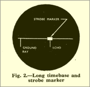
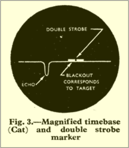
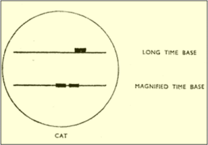
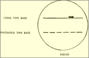
The display consists of two CRT presentations. On one of the RADAR screens is a timebase of some 400 miles length which is known as the long timebase (fig. 2). On this timebase appears the ground ray (at the beginning) and the return pulse from the aircraft (at a point depending on the aircraft range). In addition, a small part of the trace has extra brightness (strobe marker). This strobe marker can be moved at will along the trace and it is the function of the other tube to give a magnified picture of the section of the long timebase so brightened. This second presentation, a timebase of something like 3 miles length, is known as the magnified timebase (fig. 3).
At a CAT station the recurrence frequency of the long timebases is 133 hz and also the ground rays which appear at the beginning of each long timebase.
On the magnified timebase trace appear two brilliance markers separated by a small interval. These are known as the double strobe markers (fig. 3).
The gap between the twin strobes may be positioned accurately to correspond to target range, it is the function of the equipment, the aircraft receiver which is used to trigger the pulse repeater transmitter, to compare the position of the aircraft return signal with the positions of the twin strobes. The two strobes define two zones, one to the inside of the target circle and one on the outside. The comparing circuits on the ground are very sensitive and can detect even the slightest difference in time overlap of the aircraft signal with the two strobe zones. Therefore, the circuits see automatically whether the aircraft is too close to, or too far from, the CAT station.
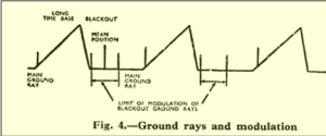
A further set of pulses is now sent out from the CAT station. These are sent out during the blackout period, so that they cause no interference to the operator. The actual position occupied by the pulses in the blackout period is controlled by the circuit which compares the position of the return pulse with the double strobes.
If the aircraft is at correct range from the CAT station, then these second pulses remain steady at a position one-quarter the way into the blackout period. This is their mean position. As the aircraft deviates from the correct track these pulses are space modulated in a dot-dash manner about their mean position. Extreme modulation takes them from the beginning of the blackout period to halfway through the black-out (fig.4). 3
Introduction to Early RADAR
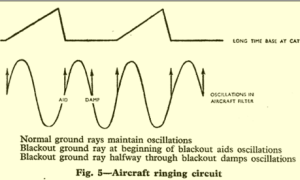
The aircraft filter, a double filter, consists of a ringing circuit tuned to 266 hz This will be maintained in oscillation by the normal pulses sent from the ground. At the same time the second type of pulses from the ground will, according to their position, reinforce or damp down these oscillations. Therefore, the filter will convert dot-dash space modulation of the pulses into dot-dash amplitude modulator for the pilot. See fig. 5.
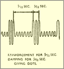
To give an example: if the aircraft is too close to the CAT station, then the blackout ground rays spend about 0.083 second at the beginning of the blackout and then about 0.42 second half-way through the black-out. In the case of extreme modulation, the filter oscillations are reinforced for 0.083 second and damped for 0.42 second. This results in a series of dots heard in the aircraft (fig. 6B)
The extent of swing of the pulses is governed by the error in range of the aircraft and so the amplitude of dots or dashes will tell the pilot the extent of his error. When he is on the correct track there is no space modulation and so a constant amplitude from the aircraft filter.
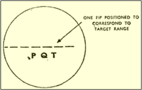
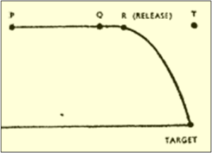
A MOUSE station has both long and magnified timebases as before. However, on the latter, a series of equidistant blackout pips appear, replacing the double strobe pulses of the CAT (fig. 7(a)). These pips can be positioned on the trace so that one of their number corresponds to target range and the others then mark out constant intervals from the target range such as PQ and QT (fig. 7(b)). The general principle adopted is that the aircraft is timed as it covers the distance PQ and information derived from this timing (velocity of aircraft) is then used to enable the bombs to be released at a point R in the interval QT, so that they actually fall on the target (fig. 7(b)). Again, most of this work is done automatically.
The recurrence frequency of the MOUSE long timebase is 97 hz and pulses are sent out at the beginning of this timebase and at the beginning of the blackout period.
The aircraft filter has a ringing circuit at 194 hz feeding the bomb-aimer’s headphones, and this will clearly be kept ringing at maximum amplitude by the Mouse pulses received. The release signal is given by a complete break in transmission. CAT and MOUSE arrays are directed towards the target area.
Mk. II F (FGRI.5606)
This uses the same display scheme as for Mk. I and, in fact, differs from the latter only in radio-frequency. It uses centimetre waves (about 9.3 cm.). The transmitter used normally is an American ASG type converted for ground use 3.
Mk. II MS
This, again, uses the same principles as the Mk. I equipment. It has been possible, however, to put the equipment into a smaller space, and an interesting feature is that both long and magnified timebases are displayed on one tube (fig. 8). The equipment is designed to work with a transmitter on 1 metre or on a centimetre wavelength. The Mk. II MS is mobile (being housed in a trailer)
Mk. II M (MGRI.5539)
This equipment has timing circuits which are completely different from those in the earlier type. A console display is used mounting two tubes.
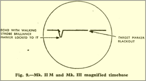
These show respectively a long timebase with strobe marker and a magnified timebase. The magnified timebase display is now the same for both CAT and MOUSE stations. A short blackout pip is used to mark out the target range and in addition there is a short brilliance marker known as the walking strobe pulse (fig. 9). This walking strobe has the property that it can lock to and follow any selected aircraft echo as it moves across the trace (compare the walking strobe in AI Mk. VI).
Circuits then translate both range and velocity of the aircraft echo into DC voltages which are used to control those circuits which send signals to the aircraft (for either CAT or MOUSE operation).
Mk. II M (continued)
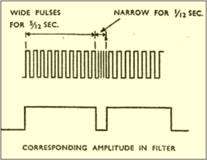
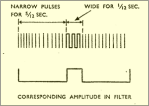
Space modulation of alternate ground rays is not now employed Instead the pulse transmission is width modulated in accordance with signals to be sent. The modulation of pulse width is done in a dot-dash manner, width now being modulated exactly as position of the black-out ground rays was modulated previously (see fig. 10). Consequently, at a CAT station, for example, pulses of constant width are sent out if the aircraft is on track.
The aircraft filters are now adjusted so that they convert dot-dash width modulation into dot-dash amplitude modulation for the pilot and bomb-aimer to hear.
The Pulse Repetition Frequency (p.r.f). can now be varied to a certain extent for different station pairs, but they are always of the order mentioned before (97 hz for MOUSE and 133 hz for CAT. The transmitter is on a centimetre wavelength (about 9.3 cm.). The equipment is mobile, being housed within a trailer.
Mk. III (FGRI.5565)
Oboe Mk. III is really the fixed version of Oboe Mk. II M, a feature being the provision for multichannel working. The method adopted for multichannel working is to have a number of display consoles similar to those of Mk. II M, and a calibrator rack supplying a number of Pulse Repetition Frequency (p.r.f.)’s. A common transmitter is used for all the p.r.f. channels, each pulse train being width-modulated by the relevant console and control gear. Apart from the fact that a common transmitter is used, a Mk. III station can be said to be a Mk. II M station reproduced n times, where n is the number of p.r.f.’s used. Mk. III employs a wave-length of about 9.3 cm.
It will be seen that both in Mk. II M and Mk. III operation, where muliple Pulse Repetition Frequency (p.r.f.) pairs may be used, it is necessary to be able to discriminate between these p.r.f. pairs in the aircraft. It is necessary, therefore, for the aircraft to carry what is known as a Pulse Repetition Frequency (p.r.f.) selector.
Summmary of Aircraft Equipment
In summary, the aircraft equipment must contain a receiver which triggers the pulse repeating transmitter and which feeds also to a double filter for station selection. For multi- channel operation a p.r.f. selector is needed.
The early gear was known as the Pea-cock equipment (ARI.5513) and worked on the 1 metre band.
For centimetre working Album Leaf equipment is used (ARI.5582). This uses an American ASG type transmitter. Album Leaf is now termed Oboe Mk. II.
Oboe Mk. III is like Oboe Mk. II fitted with a p.r.f. selector, and works with width-modulated ground stations 3 .
Conclusion
Oboe was a British aerial blind bombing targeting system in World War II, based on radio transponder technology. Prior to a mission, a circle was drawn around one of the Oboe transmitters so that it passed over the selected target. The bombers, one at a time, would then attempt to fly along this path towards the target. The Oboe operator in England would use the equipment to see if the bomber strayed from the path, and give the pilot instructions on how to regain it.
The MkI Oboe Navigation system was upgraded in early 1944 by a TRE team lead by Dr F. E. Jones, the system was known as the Mk. II F (FGRI.5606) This used the same display scheme as for Mk. I and, in fact, differs from the latter only in radio-frequency. It used centimetre waves (about 9.3 cm.). The 3Ghz transmitter normally used was an American ASG type converted for ground use 1.
A team of TRE scientist at TRE Malvern, formerly based at Leeson House, Swanage, reviewed this new model and were disenchanted with its performance and was surprised with the results then being achieved 2.
In early May 1944, the next mission was to bomb gun emplacements, a target a hundred times smaller than the train marshalling yards at Hamm Germany.
The TRE team decided to examine an operational Oboe station’s equipment. At Walmer, Deal, they quickly found after reading the documentation that the Master Oscillator was not accurate enough for the task in hand and the display strobe control, used for accuracy of distance and airspeed measurements, was very coarse and unstable 2.
A TRE Oboe team member, Mr Reg Batt collected a new set of quartz crystals from the Post Office Research Department, Dollis Hill, North London and went to each of the Oboe stations to train the Pilot Officers in installing the modification, using the master test oscillator, this was two feet high and weighed 50 Kg., supplied by the Dollis Hill.
On the 27 May, Swanage was the second station to be modified and on the 6 June D-Day. Trimmingham, Norfolk, was the last on the list 2
The Pathfinder aircraft, normally a Mosquito flew on a circular arc centred on the CAT station at a radius equal to the target range, the correct positional path was only 32 metres wide, allowing for much greater accuracy than competing systems like Gee. German radar operators spotted this curved path the Mosquito followed and called the system “Boomerang” after the arc segment left on their RADAR displays as the aircraft appeared and disappeared out of range.
The directional instructions transmitted by the Cat station was in Morse Code, these signals to the Mosquito denoted the Distance from the curved Path.
Examples were: X ( -..-), Y (-.–) and Z (–..) denoting 20 miles, 10 miles and 5 miles, respectively. Once the Mosquito was following the positional arc, the Mosquito pilot would be warned, by a string of Dots if the aircraft veered to the West and a string of Dashes if to the East.
Oboe was used to guide Pathfinder bombers to drop their Target Indicators at the initial stages of the raid. The following bombers would use the markers as a reference for conventional bombsights. Individual aircraft were also used to bomb point targets.
Gee, a passive system that could be used by an unlimited number of aircraft, remained in use for local guidance over the UK even after Oboe became widely used for bombing.
Various Morse letters could also be sent, for example to notify the aircraft crew that the Mosquito was within a specific range of the target. The Mouse station sent five dots and a dash to indicate bomb release. Other Morse letters were:
A (.-), B (-…) C (-.-.) D (-..) denoting 10 minutes to target, 8 minutes to target, 6 minutes to target–confirm ground station, 3 minutes – steady on 190 degrees, respectively.
The Mouse station included a bombsight computer, known as “Micestro”, to determine the proper release time, there being no logic in carrying the bombsight on the Mosquito when it was under the control of the ground station.
It took the Germans more than a year to discover the mystery of the system. Oboe was cracked by engineer H. Widdra (who had already detected the British “Pip Squeak” IFF in 1940) at the end of August 1943 at the RF tracking station “Maibaum”, located in Kettwig near Essen, while the British bombers attacked the steelworks of “Bochumer Verein” 4.
In 1944, the Germans tried to jam 1.5 metre / 200 MHz Mk 1 Oboe signals, though by the time they did the British had moved on to the 10 cm / 3 GHz Mk.II Oboe and were using the old transmissions as a ruse. This was discovered in July 1944 by the Luftwaffe after an RAF operator failed to properly mark a drop using the Mk.1 signals 4.
References
- Purbeck Radar Trust 2015 Biography ~ Alex Reeves CBE [Online] Available from: www.purbeckradar.org.uk
- Batt R. 1991 The Radar Army, Winning the War of the Airways London, Robert Hale Ltd
- Air Ministry 1946 (Declassified 1977) Introductory Survey of Radar Part II Air Publication 1093D Vol. 1 Chap 5
- Goebel G. 2004 Oboe Navigation: Radio Navigation Systems: Operational History [Online] Available from: https://military-history.fandom.com/wiki/Oboe_(navigation)#Technical_details
