Trials of the GEE system had been made over Britain and out into the Atlantic, and it worked very well. Bomber Command, however, still had misgivings, and would only be convinced if it could be tried out over Germany. The Command therefore fitted trial receivers into three aircraft and proceeded, without telling the Air Staff, to fly them over Germany.
Introduction to GEE Navigation
In August 1941, Air Command had an emergency, R.V. Jones from Air Scientific Intelligence was summoned to Sir Henry Tizard to discuss a new radio navigational aid that had been developed by R. J. Dippy in 1940. Although, it had been turned down in 1938, partly because it was believed that the range of radio devices would not be great enough to permit accurate navigation over Germany and partly because Bomber Command and others were convinced that these radio aids were not needed.
The situation had now changed, a report from Winston Churchill’s scientific advisor, Lindemann’s Secretary D. B. M.Butt, had located photographs taken over the Ruhr Germany that proved only a tenth of R.A.F. bombers were within five miles of their target and inaccuracies in our bombing had prompted the Command to consider radio devices despite the fact that various senior officers had hitherto termed them an ‘adventitious aids’ 1.
Trials of the GEE system had been made over Britain and out into the Atlantic and it worked very well. Bomber Command, however, still had misgivings and would only be convinced if it could be tried out over Germany. Therefore, Bomber Command fitted trial GEE receivers into three aircraft and proceeded, without telling the Air Staff, to fly them over Germany.
The crews reported that the accuracy was very good and they were now able to find their way. Bomber Command then decided to use these three aircraft as primitive pathfinders for the rest of the bomber force, again without telling the Air Staff 1.
Alas, on 13th August 1941 one of these pathfinder aircraft from No. 115 Squadron was missing after leading a raid on Hanover. Bomber Command had now repeated the 1940 error of the Germans, this was a serious example, the wreckage from the aircraft could provide the Germans with information about the GEE system, which was nearly ready for use, but it would not be available, apart from the three prototype receivers, until March 1942, some seven months later.
Tizard asked Dr R. V. Jones to assess how much the Germans might have discovered. Jones guessed that there was roughly a one in three chance that the Germans had captured the receiver, although, this was probably damaged because it had been fitted with demolition charges. It was unlikely that the Germans would have, so far, recognised the pulse transmissions from the ground stations in England as being associated with a Navigational System 1.
An extract from R. V. Jones 1974 book Most Secret War describes the method of obfuscation deployed:
…Jones’ plan involved masking of any clues that the Germans might have already gathered or would gather in the future regarding the true nature of Gee, and second the planting of other clues to make them think that we were adopting an entirely different technique, since we could not avoid providing clues that some kind of new equipment was going to be installed in our bombers. The first step was to get the word ‘Gee’ abolished. The next was to get the type number changed from one in the ‘R3000 series, which indicated its true nature as a receiver of pulse-type transmissions, which the Germans could have known from the airborne radar equipment that they had already captured (I.F.F. and A.S.V.). The new type number should be one in the ordinary communications series, and TR1335′ was chosen, since this would suggest a new transmitter/receiver system for radio telegraphy or telephony.
This solved two problems: The Germans would therefore have a long warning that something new was coming along, because by changing the type number of a receiver of pulse-type transmissions to transmitter/receiver system was misleading. The British turned an awkward situation to an advantage.
Finally, the Gee transmitting stations in England were camouflaged to look like ordinary radar stations by providing them with extra masts and by removing the exact synchronization of their pulses which might otherwise have given a clue had the German interception service been alert enough to spot it 1.
Since it was likely that the Germans would learn that the British were introducing some new radio navigational system, what better than to flatter them into thinking that we were going to copy them and use beams? 1
The British had already made some beam transmitters to give our bombers a line when they were attacking the German naval units in Brest, these beam transmitters were commandeered and re-erected on the east coast of England; Jones gave them the title of ‘Jay beams’. The new bombing system was to be called ‘Jay’ and they hoped that if the Germans had previously overheard British prisoners-of-war talking about Jay they knew the prisoners were referring to the new beam radar. Incidentally, the German Agents resident in England were thanked by their German masters for this new valuable information.
Jones did not know whether or not the hoax would be successful, and the R.A.F. might therefore hope for perhaps three months’ life. In fact, large-scale Gee operations started on 8th March 1942, and no jamming was experienced until nearly five months afterwards. The R.A.F. had therefore obtained considerably more than the three months mentioned.
British pilot prisoners were still being interrogated about the Jay beams as late as July. A German account of a meeting in Berlin on 26th May 1942 to discuss the new British navigational system. The Intelligence Officer in charge of the investigation was Engineer-Colonel Schwenke, he reported that:
We have also carried out a systematic interrogation of prisoners. The following facts have come to light. As a result of the extensive use by us of the Knickebein and X-and Y-Gerät systems these devices fell into British hands; this was because we did not fit demolition charges.
In mid-1940, the British placed orders for the immediate construction of copies of the Knickebein and a year later, in August or September 1941, these were ready for service. The British found it comparatively simple to copy the German set, as the airborne Knickebein used the installation for (Lorenz) blind beam (airfield approach) receivers, and the British had obtained the licence for the Lorenz set before the war. From the interrogation of prisoners, we know that this system was used under the designation ‘Julius’ 1.
He went on to tell how captured Gee sets now indicated that we had also developed another system, and then gave an accurate account of the genuine Gee principle.
He went on to say that the Director General of Air Signals, General Martini, was going to call a conference on the question of jamming Gee.
Therefore, the jammers for Gee were not even designed more than two months after we were using it on a large scale. Meanwhile the German Air Signals Experimental Regiment (who had operated the beam stations against us in 1940) had themselves set up listening 1
In the early part of the war, dead-reckoning and astro-navigational methods were major means of locating enemy aircraft. There were other limited Direction Finding (DF) facilities. Both of these methods are open to serious inaccuracies. The main disadvantage of the DF system was that it could easily become saturated but then considered an advanced form of radio direction finding (RDF)– a means of locating aircraft radio transmissions by identifying the direction from which they are strongest.
Today, there is Direction Finding station located in the New Forest, the site is on Ibsley common it consists of a blast wall within which the main building, a 30 feet wooden tower, would have stood.
To overcome these difficulties, radar technique was summoned and the Gee system was devised. Gee is classed as radar equipment, since it uses a pulse technique, although, it is completely different from all earlier equipment. The main difference is its only transmission is from ground stations to the aircraft, there is no transmission back from the aircraft to the ground, either repeated signal or re-radiated signal. Since the aircraft, is a receiver of radiation from the ground and does not retransmit, there is no limit to the number of aircraft that can use the system at any one time, similar in to an ordinary broadcast programme 2.
Gee-7000 was developed by Robert John Dippy at the Telecommunication Research Establishment Worth and first introduced into the service in the early part of 1941 with the aim to fit the equipment to as many aircraft as possible. The original Gee aerial was taken down in 1972 3..
General principles of operation
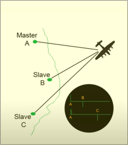
The Gee-7000 system involves locked transmission from three or more ground stations, one would be a silent Monitor, the Southern region Monitor was located at Brandy Bay, Kimmeridge, Dorset. The British Aircrew could track their location, in the air, by the measurement of path differences from these stations. The following discusses the principle of path differences.
The principle of path differences
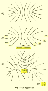
From Figure 1(A), Suppose a ground station is set up which is allowed to transmit a regular set of pulses, in the normal radar manner. An aircraft situated at P will receive these pulses a certain time after transmission.
In fact, if the letter v is the velocity of electromagnetic waves, the time t1 taken for a pulse to travel from A to P is:
t1= AP/v
Suppose now that at the same time, the pulse from A is picked up at a second ground station situated at B, and that this second station itself transmits a pulse at definite time T after receiving the A pulse. Then, counting as an origin for time reference, the time at which A transmits, it follows that the aircraft will receive the pulse from B after a time
(where T is the inevitable delay between reception of an A pulse at B and transmission from B).
It will be noticed that t, is made up of three parts :-
(1) Time of travel from A to B.
(2) Delay introduced at B.
(3) Time of travel from B to P.
It will be seen that t2 > t1.
The equipment carried in the aircraft enables the navigator to measure rapidly the time difference between the arrival of the A and B pulses, that is, the quantity to t2-t1.
Now,
Now, t2-t1 = AB/v + T + PB/v – AP/v
The quantities AB, and v are known constants, and the equipment at a ground station enables T also to be kept constant. It follows, that if t1-t2 is known, (PB-AP) will also be known 2.
The best way to use this information is clearly to draw on a map containing A and B, a set of curves of constant path difference from those points. Along such a curve BP – AP will remain constant, and so therefore will t2 – t1 remain constant. Each of the curves is labelled with the appropriate value of t2 – t1, which applies to it.
All that has then to be done by the navigator is to measure t2 – t1 and this will immediately enable him to fix himself along one or other of the curves in the system.
It may be shown that these curves of constant path difference are hyperbolae about A and B as foci 2.
Example
Assuming the separation of the A and B stations to be 100 miles, a normal figure. Assume also that the delay introduced at the B station is 500 microseconds. As a further approximation, say the velocity of electromagnetic waves is such that it takes 5 microseconds for them to cover one mile. Then it can easily be seen that everywhere along AB produced (fig. 1(B)) a constant time difference of 500 microseconds will be observed between reception of the A and B pulses,
t1 = AP/v = (AB + BP)/v
Similarly, along BA produced, a constant time difference of 1500 microseconds will be observed. Finally, the perpendicular bisector of AB will be the line of 1000 microseconds time difference.
These three instances are those in which the hyperbolae mentioned previously degenerate into straight lines. All the other cases are, true hyperbolae as shown in fig. 1(B), and all have time-difference values lying between 500 and 1500 microseconds. An important fact, there is a definite upper limit (1500 microseconds) to the time-difference observed anywhere.
This fact is of importance in determining the length of timebase to be used in the display scheme, and means that (as compared with all other radar equipments) maximum range is not limited in any way by the length of timebase. Provided our timebases are of greater length than 1500 microseconds, an A pulse displayed to the extreme left of a timebase will give rise to a B pulse always on that same timebase wherever the aircraft may be. In fact, a timebase length of 2 milliseconds (including blackout period) is used.
The hyperbolic mesh
To obtain a “fix,” it is necessary to introduce a third ground station C (fig. 1(C)) which functions in the same manner as the B station, and a further set of hyperbolae can be drawn, this time with A and C as foci. By measuring the ime difference between arrival of the A and C pulses the navigator can fix the aircraft along one of this family of
curves.
The position of the aircraft can be fixed by measuring the (A – B) and the (A – C) time difference, and by finding where the corresponding curves in the two families of hyperbolae intersect..
The hyperbolic curves are very often called lattice lines and the whole system is said to provide a hyperbolic mesh over the map.
Ambiguity
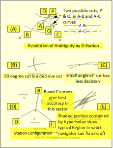
Ambiguity may possibly arise because any two branch hyperbolae from the two systems have two points of intersection, (Fig. 2(a)). Difficulty may therefore be experienced in this respect, particularly in the vicinity of the A station. This can be overcome by introducing a fourth station D similar to the B and C stations. For though the A-B and A-C curves may intersect at two points P and Q, the navigator by measuring the A-D time difference can tell which is the correct point to take 2.
Accuracy
In the main the accuracy of the system is determined by two factors:
(1) Maintenance of constant value of T at a B, C or D station (this can be done to limits of less than 0.1 microsecond); and accuracy of reading of time difference in the aircraft (this can be done to limits of about 0.5 microsecond).
(2) The number of lattice lines that can be drawn on a map with- out undue confusion, and the accuracy with which the navigator can determine their points of intersection (particularly when interpolating).
Provided pulses remain of sufficient strength, the errors introduced in (1) are appreciably independent of range. The errors introduced in (2), however, increase with range, for as the range from the ground stations increases the acute angle of cut of the hyperbolic curves will decrease 2.
With reference to fig. 2(B) and 2(C) that as the angle of cut diminishes so does the decisive nature of that cut. The optimum case will be that of a right-angled cut. If care is taken in the siteing of the D station it can be arranged that in places where the angle of cut of the A-B and A-C curves begins to fall off then a better cut is obtained with either the A-B and A-D curves or the A-C and A-D curves, (fig. 2(D)).
In the vicinity of the stations, fixes can be obtained to an accuracy of a few hundred yards. Then, as range increases, the accuracy gradually falls until at extreme range of 500 miles the navigator could, in theory, place himself somewhere within a diamond figure (fig. 2(C)), with diagonals 5 and 3 miles long.
In practice the accuracy attained is somewhat inferior to this 2.
Range and coverage
The range of Gee is limited by the power of the ground transmitters and by the height at which the aircraft can fly in order to remain within the radiation lobe despite the earth curvature.
With the present equipment, at 15,000 feet a range of 450 miles is attainable, provided no jamming is present. At greater heights and under favourable atmospheric conditions greater ranges may be possible.
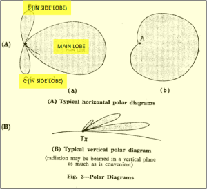
No special steps are taken to give intense beaming of the radiation from the ground, for a wide service area is desirable, compare the floodlight technique of Chain Home (CH) stations; a simple reflector system on the ground station antennae serves to throw the bulk of the radiation forward, and to cut down back-radiation see fig. 3(A).
In general a simple reflector system on the ground station antennae serves to throw the bulk of the radiation forward, and to cut down back-radiation.see Fig 3(A).
A stack of vertical dipoles is employed to provide vertically polarised radiation (= 6 metres) 2.
Monitoring of ground stations
Though, the precise value of T (the time delay introduced at B, C or D) is not particularly important; it is, however, of the utmost importance to keep it constant. Its value need not be the same for all three stations
In general an alteration in the value of T demands a corresponding change in the numbers affixed to the hyperbolic grids.
The B, C and D stations each have monitoring facilities in order to measure their individual T values, but in addition a cross-check is kept by introducing a final ground station into the scheme. This is the monitor station, and its function is to pick up pulses from the other ground stations, and to inform them if they are in error.
Ground Station Organisation
The method the scheme has been developed is the A station originates transmission, the other stations in the scheme follow it. For this reason, the A station is commonly referred to as the MASTER station and the B. C and D are referred to as the SLAVE stations, where the D is the STAR SLAVE.
A complete Gee system, as described, comprises a Master, Monitor and three slave stations. It is known as a Gee-7000 chain. In the case of the Southern Chain the Monitor was located at Brandy Bay, Kimmeridge,Wareham, Dorset.
Though the role of a Monitor station is essentially passive, it serves as the headquarters for its chain. It maintains constant telephonic communication with the other stations of the chain and through it are passed all operational messages from the Command using the system 2.
For example, the Southern chain Master was at Bulbarrow Hill, Dorset, would transmit a pulse of radio energy; when the Slave at Truleigh Hill, Sussex received the signal , it would transmit one too; after a fraction of a second delay, Bulbarrow Hill would transmit another pulse, when West Prawle, Devon received it, it would transmit another. Then the whole cycle would start again. 4
In general all chains transmit continuously, each chain having its own radio-frequency. At present there are five chains situated in Great Britain. They are, in order of erection :-
(1) Eastern Chain, with stations in central England, directed towards Holland, Belgium and N.W. Germany.
(2) Southern Chain, with stations in Southern England, directed towards France.
(3) Northern Chain, with stations in the Northern part of Scotland, directed towards the North Sea and Norway.
(4) South-Western chain, with stations in South Wales and Western England, directed towards the Bay of Biscay.
(5) North-Eastern chain, with stations in North East England, directed towards Denmark 2.
Station Identification and Presentation in the Aircraft
To enable the navigator to identify the ground stations of any one chain, a complex system of pulse recurrence frequencies is used, resulting in a rather complex timebase system.
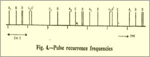
Consider the master station transmission: The master sends out steady set of pulses at a p.r.f. of 500 hz. These pulses will occur at 2 millisecond intervals, and when they are put on a time scale, divided into two-millisecond sections, they appear as in fig. 4 2.
The A pulses are now divided into two different sets; one set will be referred to as A1 set and the other A2. The division into sets is done in such a manner that A1 and A, are interleaved (again as seen in fig. 4.)
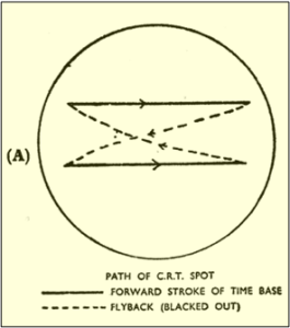
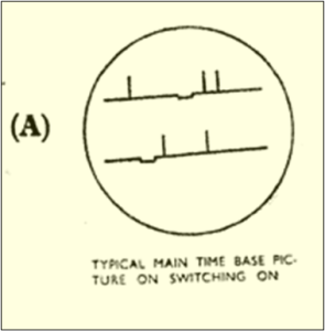
The aircraft timebase is made to run also at 500 Hz, but alternate timebase traces are deflected downwards as in fig. 5(A). It follows that a complete timebase picture takes 4 milliseconds to complete (including flyback time). Moreover it will be seen that one A pulse will appear on each of these timebase traces, (an A1 on one trace and an A2 on the other).
Since the aircraft timebase is allowed to run freely, there is no means of estimating when the equipment is first switched on, where exactly the A pulses will be, relative to the timebase.
However, the navigator can control the timebase phase, which controls the starting time of the timebase. By adjustment of this control, therefore, the navigator can set the equipment so that the A station pulses appear at the extreme left of the timebases.
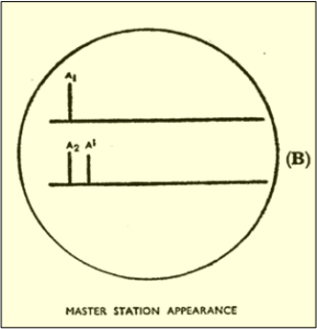
It is impossible for the navigator so far to distinguish between A1 and A2; to help him do this, however, an auxiliary transmission Ai is sent out from the master station. This is transmitted on a p.r.f. of 125 c/s, and will therefore occur once for every fourth main A pulse. It is phased so that it occurs at about 100 μs after every second A, pulse. The general appearance of the master transmission on the aircraft timebase is as in fig. 5(B).
Station Identification and Presentation in the Aircraft cont.
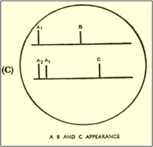
Notice that even though an A¹ pulse appears after only every other A2 an impression of continuity will be obtained in the picture as in fig. 5(C). However, A¹ will appear somewhat less brilliant than the other pulses, because the CRT spot only paints a pulse picture on every other trace, and for this reason A¹ is sometimes referred to as the A ghost or A shadow pulse rather than A identification pulse.
It is stressed that the A pulses can occupy any position on the timebase initially, but that the timebase phasing control should always be adjusted so that the single A pulse (i.e. A1) stands at the extreme left of the top trace 2.
The sole purpose of the pulse A1, is to enable the navigator to differentiate between A1 and A2, for a reason which follows.
By employing a suitable filter, Slave Station B is able to retransmit only the A1, set of pulses, consequently the p.r.f. of the B station is 250 hz; it will be seen that the delay introduced at B is less than 500 microseconds, so that wherever an aircraft maybe it will always receive a B pulse not more than 1,500 microseconds after the A9 pulse.
In a similar manner Slave Station C-slave retransmits only the A2 pulses. Its p.r.f. is therefore 250 hz also and again an aircraft will receive a C pulse always not more than about 1,500 microseconds seconds after an A2 pulse. The sequence of transmission can be seen on reference to fig. 4, and the appearance on the aircraft timebase as in fig. 5(C).
Provided A1 has been moved to its conventional position at the left of the top trace, then the B pulse will always appear some way out along the top trace and the C pulse out along the bottom trace. The existence of A¹ is necessary for distinguishing between the B and C pulses. The point to remember is that C is always associated with A¹.
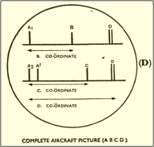
Finally, Slave Station D is made to retransmit every third A station pulse, i.e. first an A1 and then an A¹. Its p.r.f. is therefore 166 2/3 hz and it will appear on every third timebase trace, (fig. 4 and fig. 5(D)).The D transmits a double pulse
By virtue of its p.r.f. the D pulses will only occur on every other top trace and on every other bottom trace, but as far as the eye can perceive it will appear on each trace like A¹. It should be noted, however, that if D and A¹ could be examined closely they would be found not to break the base-line of the trace.
46. Moreover fig. 5(D) indicates the time to be measured to give the B, C and D co-ordinates of the fix. For this measurement it is necessary to have some form of time calibration on the timebase traces, as explained later 2.
Strobing
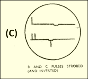
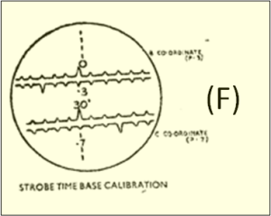
On examination of the aircraft timebase it will be noticed that there are two small troughs, one on the top trace and one on the bottom (fig. 6(D)), and that signals occurring in these troughs are inverted. The timebase presentation that we have described so far is known as the Main Timebase or MTB.
In order to achieve greater accuracy in the measurement of time intervals shown in fig. 5(D), a system of strobing is used. Strobing enables a small section of the trace to be selected and to be speeded up in the X direction. In the Gee indicator it is possible to select four small parts of the MTB for such magnification:
(1) The first 80 microseconds of the top main timebase (the A, strobe).
(2) The first 80 microseconds of the bottom main timebase (the A2 strobe).
(3) Any 80 microseconds of the top main timebase (the B strobe).
(4) Any 80 microseconds of the bottom main timebase (the C strobe).
The first two of these strobes are fixed in position. The B and C strobes can, however, be positioned at will along their respective traces (two position controls, coarse an fine, being provided for each strobe). It is therefore necessary to have the positions of the B and C strobes. marked out on the MTB. For this reason the two troughs are provided. These troughs can therefore be moved in position along their traces by means of the B and C strobe position controls respectively.
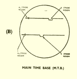
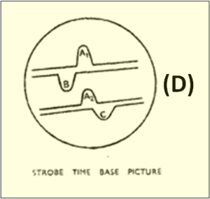
The four 80 microseconds intervals mentioned above can be shown in an enlarged form by using the timebase change-over switch. Normally this switch enables the MTB to be displayed on the CRT, but another position is provided to give us the strobe timebase or Strobe Timebase (STB) picture. (figs. 6(B) and 6(C)). The timebase now has four traces, each lasting about 80 microseconds. Reading downwards these give a magnified version of the A1, B, A2 and C strobe regions of the MTB.
It follows that any pulse occurring in any one strobe region of the MTB will appear in a magnified form on the corresponding STB trace. Signals during the B and C strobe intervals remain inverted, as on the MTB 2.
Calibration
Both types of timebase can be calibrated for time by X-deflection pips. A calibration switch enables signals to be removed from the trace and calibration applied instead.
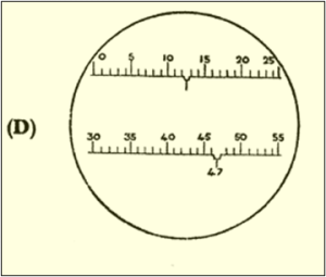
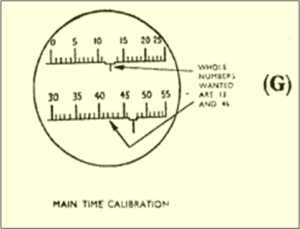
On the MTB there is a set of pips with every fifth one of greater amplitude for ease in counting (fig. 6(D)). The pips on the top trace are numbered from 0 to 25 and those on the bottom from 30 to 55 (5 pips are lost in each flyback period, which of course is blacked out).
These pips are 663 microseconds apart, but for convenience 66 microseconds is called Gee unit of time. It should be noted here that all maps are drawn and all operational instructions given in reference to Gee units of time. Pips on the MTB are therefore spaced at unit intervals 2.
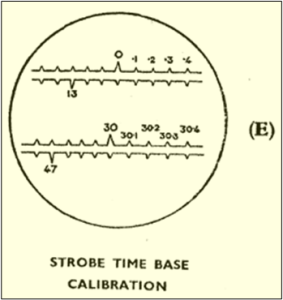
The Strobe Timebase (STB) is calibrated with pips occurring at 1/10 Gee unit intervals, with every tenth pip of greater amplitude (unit pips). The large pips on the A1 and A2 strobes are respectively the same as pips 0 and 30 in the A1 and A2 strobe regions of the MTB. As an example, if fig. 6(E) is the strobe picture of fig. 6(D), the unit pips on the B and C strobes there are 13 and 47 respectively. Note that calibration pips, as well as signals are inverted during the B and C strobe periods 2.
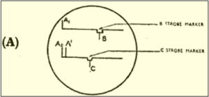
Fig. 6A Strobe Markers showing B and C Pulses Inverted Reproduced by kind permission of Philip Judkins
Taking a Fix
Since there is a slight instability inherent in the frequency of the aircraft timebase, it is found impossible to keep received pulse exactly stationary on the trace for any length of time. It is thus impossible to set A1 exactly at the zero pip and read off the calibration number under the B pulse. A differential method is needed (subtraction by sliding graduated scales against one another).
The procedure adopted for taking a fix is as follows (for B and C stations).
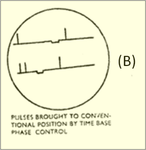
(1) Pick out single A pulse on MTB (see fig. 7(A).
(2) Use TIMEBASE PHASE CONTROL to get A1, to left of top trace into the A1 strobe region. A2 will then be in A2 strobe region on the bottom trace (see fig. 7(B)).
(3) Put B strobe marker over B pulse, and C strobe marker over C pulse, see fig. 7(C). B and C pulses will not be inverted.
(4) Switch to STB when A1, A2 B and C should appear within their strobes, see fig. 7(D).
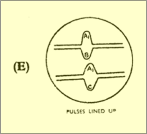
(5) By fine adjustment of strobe position controls, place B with its leading edge under A1 leading edge; and C under A2 in the same way, see fig. 7(E).
Note the time of the operation.
(6) Switch to calibration, see fig. 7(F).
(7) The number of the calibration pip on the B strobe vertically beneath A1 zero pip gives the B co-ordinate, and similarly that on the C strobe vertically beneath A2 zero pip gives the C co-ordinate. The decimal part of the fix is read on the STB.
The whole number must be obtained by reference back to MTB, see fig. 7(G) 2.
Care must be exercised in determining the whole numbers in the fix. Sometimes the whole number wanted is the one within the strobe marker; sometimes the one to the left. The example shown gives both cases. The fix gives the position of the aircraft at the time of operation (5). It will be observed that the B co-ordinates always turn out to lie between 0 and 25, while the C co-ordinate lies between 30 and 55 2.
The maps are labelled accordingly. There is therefore no possibility of confusion of the numbers as they are transferred from tube face to the map.
If a fix is required from the D station, the latter can be strobed by either of the strobes. However, the numbering of the D lines on the map runs between 30 and 55. If D is strobed on the C trace, therefore, all is well. If it is strobed on the B trace, however, 30 must be added to the number obtained 2.
Unit Details
61. Gee Mk. I (ARI 5033), comprises a receiver, type R.1324 and indicator unit, type 60. The equipment is now obsolete, being replaced by Mk. II. The general principles of the Mk. I and Mk. II aircraft equipment are the same, but Mk. II has an improved display.
Gee Mk. II (ARI 5083), comprises a receiver, type R.1355 and indicator unit, type 62.
Frequency. There are four frequency bands in use:-
20-30 Mhz.
40-50 Mhz.
50-65 Mhz.
65-80 Mhz.
Receivers are fitted with interchangeable RF units, one for each band; and the navigator can select one of five spot frequencies in each band. These spot frequencies are preset on the ground 2.
RF units:
RF stage.
Local oscillator.
Mixer.
Main receiver: 5 IF stages at 7.5 Mhz.
Diode second detector.
VF amplifier.
Cathode follower output.
The gain control is on the indicator unit
Supply: 80 volt, 1,600 Hz engine-driven generator.
Voltage control panel: Type 3.
Aerial. λ/4 whip aerial and matching unit into receiver 2.
Ground equipment
The master station possesses a transmitter and the associated drive equipment.
At a Slave Station it is necessary to have both a receiver, to receive locking pulses from the Master and a transmitter to send on pulses to the aircraft. The receiver contains a monitoring section for measuring the time delay introduced at that station.
The display is as shown in fig. 8(A) and fig. 8(B). A main time- base with a step is used and this is calibrated with unit markers in the form of brilliance modulation. There are three strobes, their positions being indicated by brilliance markers. One of them can be positioned over the step, one along the rest of the top trace and one along the bottom trace.
The strobe timebase is calibrated by unit and 1/10 unit brilliance markers; there now being three strobe timebases, corresponding to the three strobe markers (this type of display was used in the airborne Mk. I equipment).
The slave station transmitter pulse is displayed on the visual display as well as those coming from the other stations, and the equipment enables the local pulse to be sent out a fixed time after reception of the A pulses.
A Monitor Station does essentially the same thing as an aircraft observer, but since its position is known, errors at a slave station can be corrected 2.
Units
Transmitters. T.1348 (M.B.3 modified), or T.1356 or G.L. type transmitter
Output: 300kW
Oscillators: VT 58’s in push-pull followed by push-pull power amplification in two VT114 A’s
Frequency. As for aircraft equipment
Aerials (in general) Floodlight technique. Vertically stacked dipoles with reflectors to throw main lobe forward.
Wide-band aerials now used frequently to avoid matching difficulties as frequencies are changed 2.
Receivers.
R.1363 (Slave). R.1364 (Monitor).
Aerials.
1. Vertically stacked dipoles, beamed towards master station. (Slave normally in a side-lobe of the master) alternatively.
2. Inverted V aerials, the plane of which contains the master station 2.
Loran (Long Range Navigation) Equipment
General principle
This is the American counterpart of Gee and is based on the British equipment. The same principle of hyperbolae is used, but the ground station arrangement is somewhat different.
Ground stations were erected and they work in inter- laced pairs. Any one station acts as a slave for one of its neighbours and as a master for its other neighbour. Different master-slave pairs work on different pulse recurrence frequencies and the aircraft timebase can be run at any one of these p.r.f.’s. Thus, any one station-pair can be picked up at any one time. This will give one co-ordinate of the fix and the other must be obtained by switching to a different timebase speed. This means, of course, that only a running fix can be taken, one co-ordinate after another 2.
Other details
Frequency. Around 2 Mhz.
P.R.F: Different for each pair but around 25 c/s.
Range: 600 miles using direct radiation: 1,200 miles under favourable atmospheric conditions by using waves reflected from the E-layer.
Accuracy On the direct ray, comparable with Gee: on the reflected ray, errors approximately doubled.
The Loran aircraft equipment is made to conform in shape, size and cable connections with the Gee equipment to enable rapid interchanges to be made 2.
S.S. Loran
SS Loran is an adaptation of Loran, which is suitable for use by surface craft. For a summary of recent Marks of Gee-7000, Gee-H and Loran equipment 2.
THE GEE-H SYSTEM
The Gee-H system describes the Gee airborne equipment with type 100 ground stations, employing the H-principle 2.
General principles
The Gee-H system applies the principle of the Radar Beacon to accurate blind bombing and precision navigation. Two ground beacons or transponders at the ends of a base line respond to interrogating pulses emitted by the aircraft requiring a fix for its position. The beacons re- transmit pulses on another frequency, with negligible delay, to the air- craft, and these pulses are received by the Gee receiver of the aircraft and displayed on a linear timebase. The aircraft is thus able to find its range from the beacons whose positions are known and to find its own position from a range cut.
This system is more accurate than the Gee-7000 system and should not give an error greater than 300-400 yards at a range of 250 miles, but its aircraft handling capacity is lower, the maximum number that can be handled at one time being 50.
The beacons or H-beacons (AMES, type 100) comprise a receiver R.1441 and a transmitter T.1488.
The aircraft equipment comprises a Gee set, slightly modified, a transmitter and modulator, and auxiliary devices. An aircraft carrying this equipment is able both to navigate by using the type 7000 ground stations (Gee-navigation) or by interrogating the AMES, type 100 ground beacons (Gee-H navigation).
The procedure for obtaining a Gee-H fix is very similar to that for finding a Gee fix, and again involves the lining up of pulses on the time base of the display tube. The appearance of the Gee time base is approximately preserved in Gee-H but the airborne transmitter is synchronised to pulse at the start of each time base.
The responses returned by the beacons appear on the time base and the navigator notes their ranges from their positions relative to the aircraft transmitter pulse which appears at the beginning of the time base. The technique of ‘lining up” and strobing is the same as that used in Gee 2.
To avoid saturating the ground beacons which would occur if the aircraft transmitted at 500 c/s, the normal recurrence rate of a Gee time base, eight out of every ten time bases and transmitter pulses are suppressed. The interrogating pulses are therefore emitted in pairs at the recurrence rate of 50 pairs per second 2.
To avoid mutual interference between aircraft using the same beacons, the recurrence rate is actually varied about 50 pairs per second as a mean value. Only the beacon response excited by its own transmitter then appears stationary on the time base.
As it is necessary to associate the two beacon responses with their correct ground stations, one of the latter codes its responses by delaying its return periodically. The result is that the response from this ground station moves periodically a small distance to the right of its main position on the timebase of the aircraft receiver 2.
The normal Gee time base runs for 1660 microseconds and is followed by a blackout interval of 340 microseconds before the next time base.
Since a radar mile of range is equivalent to 10 microseconds of the time base, the maximum range, if a normal Gee time base were employed, would be 166 miles. Responses from beacons at ranges lying between 166 miles and 200 miles would fall in the blackout interval; and those from beacons at ranges greater than 200 miles, on the second timebase 2.
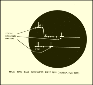
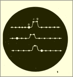
Fig. 8A Main Timebase Showing First few Calibration PIPS. Reproduced by kind permission of Philip Judkins
To permit the aircraft to receive all beacon responses up to the maximum operational range of about 360 miles, the normal Gee timebase is modified by introduction of an intricate system of switching; details will be found in the appropriate technical manuals 2.
Marks of Gee-H
Mk. I: (ARI.5525) is an interim airborne equipment.
Mk. II: (ARI.5597). Includes a high-power transmitter (type T1629). and a redesigned indicator unit (type 166) which affords Rebecca and BABS facilities.
ARI.5611: is a combination of Gee-H Mk. II and Rebecca Mk. II U.
Gee-H ground installations
AMES, type 100 is a heavy ground beacon equipment but mobile forms exist 2.
AMES, type 100–Light transportable, is a combination of types 100 and 7000 equipment which can provide both a Gee and a Gee-H service to aircraft. It is designed to be transportable by van or by air and is tropicalised 2.
Three ground stations form a normal Gee chain and any two of the three can function as a pair of Gee-H beacons.
A common transmitter is shared between the type 700 and type 100 equipment at a ground station.
The equipment provides close range support in army co-operation with Gee for navigation and Gee-H for blind bombing.
For special tasks the equipment may be resolved into separate type 7000 and type 100 stations 2.
SHORAN
Shoran-(Short Range Navigation), is an American blind- bombing equipment using the H principle 2.
AN/CPN-2 is the ground equipment.
AN/APN-3 is the airborne equipment. Radar information is automatically fed to computers which control the aircraft and release the bombs
Gee Navigation Deployment during the Hamburg Raid 24/25 July 1943
This raid was the first deployment of Window RADAR jamming, developed by the Physicist Joan Curran at TRE Leeson House Langton Matravers, Swanage, Dorset. It was imperative that the attacking bombers were in a specific Luftwaffe RADAR Box to limit the number of defending Luftwaffe night-fighters. The British armada of 791 bombers comprised of 347 Lancasters, 246 Halifaxes, 125 Stirlings and 73 Wellingtons, although, before the attack 45 of the aeroplanes returned to base because of mechanical failure 5..
In December 1940, none of the German night-fighters had RADAR specific to their role. Therefore, Generalmajor Josef Kammhuber subdivided the searchlight belt into boxes about 20 miles wide each with a radio beacon that a night-fighter would orbit while awaiting the enemy. The German defensive line, formed a barrier that attacking aircraft had to cross to their target and again on their return flight. Each box was equipped with one Freya and two Wurzburg radars, a radio beacon and a ground control station. The Freya RADAR (120-130 Mhz) directed one Wurzburg, with a short range narrow beam to track the attacking night-fighter, while the other Wurzburg tracked the incoming bomber; the Wurzburg equipment was also designed to direct the Flak guns to the targets. The deployed German night-fighter crews were instructed, via the radio beacon, by their ground controllers and forced to trust them when guided to their targets 5..
On the 24 July 1943, at an afternoon R.A.F Bomber Command briefing, the Hamburg Raid aircrew were told the weather forecast for the Hamburg raid was a 17-mph wind from the northwest.
At midnight, the bomber stream was assembled over the North Sea, a mighty armada of aircraft spread over an area 200 miles long and twenty miles wide. The bombers moved eastwards at 225 miles per hour, 3 miles per minute. The navigators plotted their ‘Gee’ fixes once every six minutes and discovered a crucial error in the previous weather forecast. The wind was from almost the opposite direction, at 12 mph; without GEE Navigation the raid would have failed because of cloud cover. The navigators corrected their bombers’ headings to compensate for the new wind, attentive German eyes followed their progress on Freya RADAR (120-130 Mhz) 5.
At 2300 hours, the big German Luftwaffe Wassermann and Mammut, (both 120-130 Mhz) early-warning RADARs, overlooking the North Sea began passing reports on the progress of the raiders. At a score of airfields in northern Germany, night-fighters and their crews were brought to readiness.
At 0015 hours, the leading bombers turned southeast into the Heligoland Bight, track 117 degrees. Four minutes later a restricted warning went out to military and civil defence headquarters, industrial buildings and hospitals: Air Danger 30 – air attack possible in the next 30 minutes. That was the cue for the local air defences to come to life. At Flak sites around Hamburg, men ran to their weapons and began to ready them for action. Covers came off, barrels rose skywards and swung round to the northwest, shells were fused and radar sets warmed up. At the airfields at Stade, Vechta and Wittmundhaven, Lüneburg, Jagel and Kastrup, night-fighters scrambled and headed out towards their waiting radio beacons 5.
At 0024 hours, the restricted alert was amended to Air Danger 15. Seven minutes later, the first public Air Raid Warning was sounded – a series of two-second siren tones. For a full minute, the rising and falling blast echoed asynchronously across the city from a hundred sirens, from Blankenese in the west to Wandsbek in the east, from Langenhorn in the north to Harburg in the heart of the docklands in the south. The inhabitants of Hamburg were not alone as they ran for their shelters; at Lübeck, Kiel and Bremen, R.A.F. Mosquitoes dropped target markers and a few small bombs in diversionary attacks. In each city, the full Flieger-alarm sent people scurrying for cover.
At 0025 hours, the leading bombers passed the 8 1⁄2-degree meridian. From then on, at one-minute intervals, the bomb aimer in each aircraft released a bundle of aluminium foil strips each one 30cm X 1.5cm centimetres, into the night sky 5. As the leading aircraft crossed the German coast the flight engineer in each bomber crawled back to the flare-chute to relieve the bomb aimer of the ‘Window’ dropping task: the bomb aimer would soon have other tasks on hand. In each Pathfinder aircraft fitted with H2S (3 Ghz), the large echo indicating the city of Hamburg slowly moved towards the centre of the screen 5.
At 0057 hours, right on time, the first yellow target markers cascaded towards the ground. The Battle of Hamburg had begun.
The first report of anything out of the ordinary came from the Hummer radar box on the island of Heligoland, this was not surprising, now the ‘Window’ had appeared together with the bomber stream on the Giant Würzburg (553-556 Mhz) radar screens. Each cloud of foil remained effective for about fifteen minutes before the strips dispersed. So, with each minute that passed, on radar the apparent strength of the raiding force of 746 bombers doubled in size 5.
Note: A wavelength at 554.5 Mhz is 54.5 centimetres, for RADAR jamming use half a wavelength of aluminium strip or 27 cm, 30cm is close enough to cause absolute havoc to Defence RADAR.
The operators at Hummer complained that they were,
‘Disturbed by many apparent point-targets looking like aircraft, either stationary or slow moving. The picking-up of genuine aircraft is made extremely difficult. Once they have been picked up it is possible to follow them, but only with difficulty.’
The Auster station on the southern tip of Sylt reported similar trouble. So, in turn, did the rest of the radar stations around Hamburg.
Circling over their appointed radio beacons, the German night-fighter crews waited with growing impatience for instructions from their ground controllers. but the ground controllers could not help them. Soon the radio transmission or ether was thick with confused appeals and exclamations:
‘The enemy are reproducing themselves.’ ‘It is impossible – too many hostiles.’
Wait a while. There are many more hostiles.’
‘I cannot control you.’
‘Try without your ground control.’
In 1943, the German night-fighters were equipped with an air-to-air radar named Lichtenstein, it was first operational in February 1942, its transmission frequency was 490 Mhz or half–wave length 30.5 cm, consequently even better matched than Wurzburg 5. and the effect of Window on the German pilot’s screen was as follows:
“Tommy flying towards us at a great speed. Distance decreasing 2000…1,500…1000…500 he has disappeared!”
At 0102 hours, the first wave of the bombers, 110 Lancaster from 1 and 5 group, arrived over the city of Hamburg. The first thing they noticed was the dreaded searchlights, usually seen shining bolt upright before tilting swiftly over to trap some unfortunate bomber, were wandering all over the sky. Now the searchlights seem to be groping blindly for their target. Where beams did cross others quickly joined them culminating into a cone of light, shining onto nothing.
The Flak gunners abandoned predicted fire and fired into the box in the sky centred on the bombers predicted release point. The chances of a shell bursting at the right time and space were remote.
With no Flak and searchlights, the raiders delivered a concentrated attack on the parts marked out for them by the Early Pathfinder aircraft.
Altogether, Bomber Command lost only 12 aircraft or 1.5% of the large attacking force this comprised of four Lancasters, four Halifaxes, three Stirlings and one Wellington, they probably fell to the night-fighters or the Flak guns.
When bombing Hamburg, the normal bomber loss was 50, so 38 bombers were saved by dropping 40 tons of Window – 92 million strips of aluminium foil!
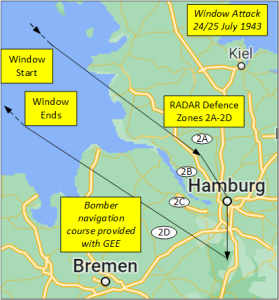
A main reason for the success of this attack was the availability of the navigation system, GEE, that allowed the aircraft navigator to plot his course accurately and maintain his position within the column that passed over only two defensive RADAR boxes 2A and 2D, inward and outward respectively, as shown in the Window Attack 24/25 July 1943 diagram 5.
References
- Jones R.V. 1998 Most Secret War: British Scientific Intelligence 1940-1945 Wordsworth Editions Ltd
- Air Ministry 1946 (Declassified 1977) Introductory Survey of Radar Part II Air Publication 1093D Vol. 1 Chap 4
- Penley J. Dean M.1979 Radar Museum Swanage The Purbeck Radar Museum Trust [Online] Available from: http://www.purbeckradar.org.uk/biography/curran_sam.htm
- Dr Judkins P Langton help saves the Nation [Online] Available from: www.Langtonia.org
- Price A. 1967 Instruments of Darkness: The History of Electronics Warfare 1939-1945 Pub: London William Kimber & Co
