(TRE) Worth
The extra-ordinary secret establishment at Worth Matravers and its Superintendent, Albert Percival Rowe (1898-1976), who controlled the Telecommunications Research Establishment (TRE) Worth during part of the Second World War 1940-42. A radar pioneer and university vice-chancellor.
German Airship LZ-130 Graf Zeppelin II’s Spy Mission flight
The German Airship LZ-130 Graf Zeppelin II’s spy mission flight over the east coast of England took place on August 2, 1939; thirty days later Germany invaded Poland, beginning World War II.
The Germans were aware that they would be in conflict with the RAF and it was imperative that they learnt the RADAR characteristics of the top secret Chain Home transmitters and relay this information back to headquarters using a large 5.5 metre dipole aerial on the 25-30 MHz band.
This spy mission was unsuccesful, they scanned the Chain Home Transmission Signal but were unable to locate the frequency because they avoided their headquarters frequency band 25-30 MHz and the Chain Home used 27Mhz
Telecommunications Research Establishment
Based on A.P. Rowe’s Obituary 1976, written by Sir Bernard Lovell 31.
Readers should reflect on the extra-ordinary secret establishment at Worth Matravers and its Superintendent, Albert Percival Rowe
(1898-1976), who controlled the Telecommunications Research Establishment (TRE) Worth during part of the Second World War 1940-42.
A radar pioneer and university vice-chancellor, born on 23 March 1898 at Launceston, Cornwall, England, son of Albert Rowe, sewing-machine agent, and his wife Mary Annie, née Goudge. Young Albert attended the Portsmouth Dockyard School and studied physics at the Royal College of Science, University of London (B.Sc. Hons, 1922). He joined a defence science unit of the Air Ministry, and lectured part time (1927-37) at the Imperial College of Science and Technology.
In 1934, Rowe was a participant in the Scientific Survey of Air Defence Committee, known as the Tizard Committee. This was chaired by Sir Henry Thomas Tizard GCB AFC FRS (1885 – 1959). In 1935, Rowe was secretary of the Committee for the Scientific Survey of Air Defence, formed under the chairmanship of Sir Henry Tizard to evaluate research in radio direction finding. In 1938-45 he was chief superintendent of the organization which became the Telecommunications Research Establishment and which led much of the development of RADAR.
In September, 1938, Rowe was appointed as head of the new Air Ministry Research Establishment (AMRE) at Bawdsey Manor, near Felixstowe, Suffolk, superseding Robert Watson-Watt who had been the head since 1936. Watson-Watt had made the original proposal for the Chain Home service in a report entitled The Detection of Aircraft by Radio Methods and executed a practical demonstration for A. P. Rowe.
With the basic network of Chain Station Home Service (CH) RADAR stations established on the east and south coasts by September, 1939, Rowe moved his establishment to Dundee on the outbreak of hostilities. His obituary states: …Only one thing concerned him for the next six years – and that was the development and deployment by the Services of RADAR systems, first to safe- guard the country and then attack the enemy.
In the spring of 1940, Rowe transferred his establishment to Worth Matravers, near Swanage, in Dorset. In May 1942, there was a possibility that the Worth Matravers site and its satellite sites at Leeson and Durnford, would be attacked by German Paratroopers and all their highly secret RADAR equipment and skilled manpower could be commandeered by the Germans. At this point Rowe hastily organised a mass exodus to Malvern College, north of Hereford on the Welsh border 31
From Rowe’s obituary there is a description of his deeds, it states: ….. From Rowe’s establishment there soon poured out a host of ground based and airborne RADAR devices which were to exert decisive influences in many of the theatres of war… it continues with a detailed list of the achievements instigated by him and a reflection of the great work undertaken by his scientists to achieve the governments objective of quashing Hitler’s objective of conquering Europe. Some of these scientists were members of the Cavendish Laboratory, a collection of 80 scientists from Cambridge University, led by Professor John Cockcroft, known as Cockcroft’s Army in 1939. In June 1940, three of those members, Mr Dee, Dr W. H. B. Skinner and Dr W. E. Burcham moved to TRE, Worth Matravers, to help tackle the 10cm RADAR development and achieved a solution to high resolution aircraft mounted RADAR 31.
From Rowe’s establishment there soon poured out a host of ground based and airborne RADAR devices which were to exert decisive influences in many of the theatres of war.
A system to detect low flying bombers The Chain Station Home Service – Low Cover (CHL), for the detection of low altitude (500 ft) aircraft. The stations consisted of a pair of broadside aerials 28ft wide by10ft high on searchlight turntables mounted on pairs of 20ft high wooden gantries over huts for separate 200 MHz transmitters and receivers. One set wasinstalled at site D at the end of St Aldhelm’s Head.
An air interception RADAR for the night fighters The first use of the Magnetron valve, the system was developed at Leeson House, Swanage. It used a parabolic dish to improve the directionality of the signal; the resulting beam was so sharply focussed, spanning about 10 degrees, that it easily avoided ground reflections at even low altitudes.
From the following Youtube link, What Happened To These RAF Bases Since WW2? designed by Forces TV, is an interesting seven minute description of RAF Bawdsey; it starts at the 13 minute mark.
GEE and Oboe navigation and bombing devices. Both developed at Worth Matravers, GEE was designed by R.J.Dippy, his original proposal was put forward when he worked at Bawdsey Manor.In late 1940, he was posted to Worth Matravers where he developed GEE, an aircraft RADAR navigation system, and then to Durnford House,a requisitioned Prep school. By March 1942 GEE was in service. Oboe a blind bombing radio navigation system, designed by Alec Reeves and assisted by Frank Jones. It was operational in late 1942.
Counter measures: developed by Mrs Joan Curran at Leeson House that completely mislead the enemy on D-Day. This counter measure code name “Window”, tricked the German Radar operators and completely mislead the enemy on D-Day. This counter measure, created an illusion of a large armada of bombers destined to an attack on the Calais area of France and a precursor of an amphibious attack in that area. What she developed was precisely cut bunches of aluminium foil that could be dropped from a few aircraft to fool the German radar, by producing echoes indistinguishable from those of an aircraft.
Original Version of Air to Surface Vessel (ASV)
The U-Boat Detection by Coastal Command Bombers equipped with ASV had been used since 1941, these used 1.5 metre wavelength, based on original work from Bawdsey.
However, the German Navy countered these attacks with the invention of a receiver called METOX that detected the transmissions from RAF aircraft. The Germans could detect 1.5 metre RADAR well before the aircraft could find the U Boat, allowing it to dive out of harm’s way. As a consequence few U-boats were sunk and shipping losses increased to unprecedented proportions. At the beginning of 1943, threatening widespread food shortages.
After the exodus to Malvern, Dr Bernard Lovell, who had been put in charge of the H2S navigation/bombing radar work at TRE Malvern. Discovered a new role for 10 centimetre RADAR, a modified variant of H2S for ASV purposes. This would improve accuracy and not be detected by METOX due to the use of microwave frequencies. Seven H2S sets were modified in the Preston laboratories at Malvern College for installation in Maritime Wellington aircraft. It was tested at Defford airport and finally fitted in the nose cone of a Wellington Coastal Command aircraft for testing, it was a success. The Germans did later recognise the higher frequency radar being deployed and produced a receiver called (NAXOS) to detect it. TRE devised a simple interim solution, the power output of the magnetron was increased and an attenuator fitted so that as soon as the U-Boat was first detected, the power was turned down while still maintaining contact. The reduction in power detected by NAXOS appeared to show that the aircraft was flying away and therefore not a threat 32.
Rowe’s obituary states a remark made by Hitler:.. the modified version known as ASV which so troubled the U-Boats that Hitler remarked in 1943 that the setback to the U-boat campaign was “due to one single technical invention of the enemy”….
Chain Home Transmitters and Receivers
On 24th September 1937, RAF Bawdsey located near Felixstowe, Suffolk, became the first fully operational Radar station in the world. Remarkably, this was only eighteen months after the first experiment, conducted by Robert Watson Watt and Arnold Wilkins, which established that by using transmitted radio waves it was possible to detect an approaching aircraft.
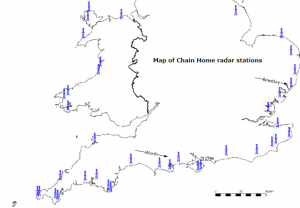
The experimental 240ft (73m) wooden receiver towers and 360ft (109m) steel transmitter towers were built and Bawdsey became the first Chain Home Radar Station. By the outbreak of World War II a chain of radar stations was in place around the coast of Britain,
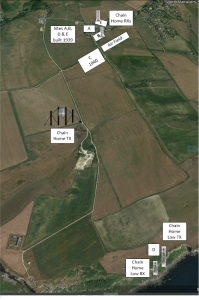
Chain Home Type 1 came in two versions, either East Coast or West Coast, east Coast sites used three or four 360ft (109m) steel lattice towers for transmission and west coast sites used 360 ft guyed masts rather than towers for supporting the aerial. RAF Bawdsey and Worth were unique in that they had Coast Defence (CD), Chain Home Low (CHL) and Chain Home (CH) equipment together on one site. Worth was a West Coast version with receiver aerial on B and E sites, placed on two wooden 240ft (75metre) masts and the transmitter’s 360 ft guyed masts were positioned 600 metres south 33
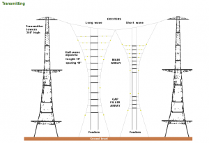
Between two transmitter towers the main aerial array was attached to the top and ground near the bottom of each tower, then 12 aerials, known as a half wave Dipole, were spaced vertically 18 feet apart. From the length of the half-wave dipole it’s straightforward to work out what frequency was used. Since half a wavelength was 18 ft (5.5m), the transmission wavelength was 11m, which corresponds to a frequency of 27 MHz. Today’s mobile phones use frequencies a hundred times higher than this, but in the late 1930s it was not a simple matter to generate 250 kW at 30 MHz, nor to design a suitable receiver.
Frequency (MHz)= 300 / wavelength (m).
To increase the transmission power another array was connected to an identical set of towers, providing a total of three arrays. The task facing the designer of an aerial system is to arrange the structure so that maximum radiated energy goes in the right direction. A simple horizontal dipole by itself won’t do – it radiates in all directions (except along its axis). The CH transmitter aerial array included a curtain of reflectors hung on the landward side to redirect this energy outwards, across the sea, to where it was useful and able to provide a return reflection signal, from approaching German aircraft, for the receiver aerials positioned behind the transmitter.
But the transmitter array acted as a floodlight – it broadcast energy out to sea over a wide angle. This meant that a station had to be built every 20 miles or so along the coast, to give continuous overlapping coverage.
It also meant that the receiving antennas had to be quite sophisticated. A simple dipole antenna would detect the echo returning from an aircraft, but would give no sense of whereabouts the aircraft was.
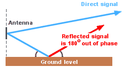
The main problem in controlling the azimuth of the radiation that is, the angle from the horizontal) is that the ground acts as a mirror, so it’s practically impossible to send the energy out horizontally. The best solution is to keep the ground as far away as possible, but some energy is always reflected from the ground. Unfortunately the reflection process adds 180 degrees of phase shift. This means that at some angle the reflected signal and the direct signal will cancel each other out. There is always an angle at which no energy is transmitted.
.
The performance of an aerial is usually illustrated by means of its polar diagramwhich shows how much energy (in relative terms) is radiated in each direction.
The performance of the CH transmitter aerials looked something like the diagram below, with a null at about 5 degrees above the horizontal. With almost no energy being transmitted at 5 degrees, the system was effectively blind in this direction.
The blind spot was removed by adding a supplementary array, known as the gap filler, suspended underneath the main array. Its polar diagram was designed to radiate maximum energy at 5 degrees 34.
At 360 feet tall, the Chain Home transmitter towers were huge – just about the same height as St. Paul’s Cathedral. This allowed their aerials to illuminate aircraft flying at 1,000 feet when they were still 40 miles away. If the enemy aircraft were considerate enough to fly at 15,000 feet, they could be seen 150 miles away.
Signal Receiving Methods
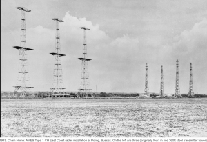
By comparing the relative strengths of the signals received by each of the crossed dipoles, using a Goniometer – a sort of adjustable phase shifter – and finding a null point, it was possible to deduce the target’s bearing. The original transmission aerial array was four aerials, but this was modified later in the war to three aerials as depicted in the following 1945 image.
Comparing the relative outputs of the pairs of aerials at different heights and correcting for the curvature of the earth) the height of the target could also be found.
It was time-consuming work, and needed concentration.
Chain Home was built to give early warning of where bomber raids were coming from, and when, so that fighter squadrons could be scrambled to intercept them instead of simply patrolling in the hope of spotting the enemy. More effective use of fighters meant that fewer would be needed, and Government was acutely aware that there might not be enough.
The Battle of Britain was fought largely in daylight. Provided the fighters could be sent to the same area of sky as the bombers, they could see the enemy and engage. If the German High Command had understood the importance of Chain Home and seriously damaged it before concentrating its attack on the cities, things may have turned out very differently. As it was, German tactics switched from daylight raids to night bombing, where cities were still relatively easy to find, but bombers were not. The radar stations could still track the bombers, but the fighters sent to meet them could not see where they were.
The CH system had two major weaknesses. It couldn’t see low-flying aircraft until they were very close, and it was so huge and heavy that it couldn’t be fitted to ships, let alone aircraft. Both these problems were a direct result of the choice of operating frequency.
Technology advanced quickly, and by 1939 a system developed by the Army CD group could deliver 25 kW pulses at 300 MHz that is, at a wavelength of just 1.5m instead of CH’s 11m. A shorter wavelength meant a smaller and lighter aerial, which permitted more beam-shaping elements, which gave a narrower beam. On trial in July 1939 the system proved able to see aircraft flying at 500 feet 25 miles away. Watson Watt was impressed, and the Air Ministry ordered 24 copies of the equipment, that became known as Chain Home Low, to plug gaps in the radar coverage around the coast.
It also proved possible to fit a variant of the 300 MHz system into an aircraft. In 1939 a Fairy Battle was fitted with quarter-wave horizontal antennas on either side of the engine, and half-wave dipoles above and below the wing. The radar operator sat behind the pilot and directed him to the target via the intercom. Air Marshal Dowding was taken on a demonstration flight and the system was shown to work. But its range was limited and the unwanted reflections from the ground were a problem.
The way forward seemed to lie in shorter and shorter wavelengths – microwaves, in other words. The problem was in 1940, nobody in the world knew how to generate large amounts of power at microwave frequencies.
