Airborne Gunlaying in Turrets
Airborne Gunlaying in Turrets (AGLT) was deployed in Heavy Bombers as a Navigation aid, accurate target detection and providing the Rear Gunner with accurate information about the position of an enemy fighter, Formally called the Code Name Village Inn, no doubt, after the Square and Compass Inn that was near the TRE site and used as a social hub by the scientists.
Introduction to Early RADAR
In 1940, Great Britain was overwhelmed by the increasing power of Nazi German forces, facing nightly attacks from the Luftwaffe and rapidly diminishing resources. Following the advice of Sir Henry Tizard, a scientist who had played a critical role in creating Britain’s first radar defence system in the 1930s, the British Prime Minister Winston Churchill commissioned a small task force comprising of both civilian and military scientists to travel to the U.S. to facilitate a technology exchange among the U.S., Great Britain, and Canada.
The scientists, who were originally stationed at the Air Ministry Research Establishment AMRE Worth Matravers, Dorset, later renamed Telecommunications Research Establishment and their manager (Taffy) Edwin Bowen, manager of the 10cm group, travelled from Britain to the United States via Canada, with an operational experimental cavity magnetron the most prized scientific war-time secret 1.
This mission – known now as the Tizard Mission – began with the simple goal of mass producing the cavity magnetron, the core technology for microwave radar. An international collaboration between the United States, Great Britain, and Canada. A catalyst for ending the war and beginning a long-lasting relationship leading to the formation of the famed Radiation Laboratory (“Rad Lab”) at MIT, as well as to MIT’s emergence as a major U.S.A federally supported research university 2
British and USA Collaboration
An example of this collaboration was the U.S.A. Massachusetts Institute of Technology (MIT) Project Two. This was an advanced gun laying system which utilised the Magnetron in the automatic search, tracking and the ability to directly aim the guns. MIT was particularly knowledgeable about this field of work within their Servomechanisms Lab. In concert, British and Canadian teams began work on versions of a simpler system that they hoped to deploy by 1942, the GL Mk. III, which was a microwave version of the earlier lobe-switching 30 to 300 megahertz, ten meters to one metre wavelengths (VHF) radar sets. The Radiation Lab kept in close contact with the Canadian team during these developments.
Two previous attempts at radar-controlled gun-laying were notable. In Britain, the 75 MHz GL Mk. I radar was used in connection with a Vickers predictor; and in the U.S., the 200 MHz SCR-268 was combined with the Sperry M-4 predictor. Neither the UK or US systems had the accuracy needed to directly lay their associated guns, due to their long VHF wavelengths of 4 metre and 1.5 metre respectively. The US delegates then mentioned the Navy’s work on a 10 cm wavelength radar, which could provide the required resolution with relatively small antennas, but their klystron tube had low power and was not practical, it was initially designed for VHF Broadcast and required external cooling and consequently not suitable for aircraft.
This was not the case with the British Cavity Magnetron, a metal vacuum tube that generates nine-centimetre radar microwaves and small enough to fit into an aircraft. These benefits were used by the Americans to develop the British prototype and mass produce the Magnetron in large quantities. The U.S. Microwave Committee, immediately switched their efforts to the magnetron; the potential of the device was obvious. They had their own examples built in US labs within weeks. The expansion of the Committee led to it being renamed the Radiation Laboratory (RadLab) in 1940. 3
The Experimental Randall and Boot Cavity Magnetron was designed at Birmingham University, UK and first demonstrated at A.M.R.E Worth Matravers and developed at Leeson House, Langton Matravers by Dr H.W.B. Skinner, Sir Bernard Lovell, Dr Burcham, Mr Jimmy Atkinson, Mr A. G Ward, Mr A. Chapman and Mr P. I. Dee. It was deployed in Heavy Bombers as a Navigation aid, accurate target detection and providing the Rear Gunner with accurate information about the position of an enemy fighter, known as Airborne Gunlaying in Turrets (AGLT), formally called the Code Name Village Inn, no doubt, after the Square and Compass Inn that was near the TRE site and used as a social hub by the scientists.
The directional properties of the Airborne Gunlaying in Turrets (AGLT), are: the gunner can open fire at an unseen target with an accuracy of about half a degree; under conditions of good night visibility, the equipment may be used in a less ambitious way by relying on visual aid for firing the guns or the gunner uses radar to find the location of the attacking fighter
AGLT has two subsidiary functions. One an audible warning, it warns the gunner and air-crew that an aircraft has been picked up in the AGLT beam, achieved by the injection of a warning note into the intercommunication system whenever an aircraft is within 4,000 feet of the bomber and inside the beam. The second function of AGLT may be summarised by stating that the equipment provides automatic range for the Mk. IIC gyro gunsight
When AGLT is used the range correction is obtained from the radar equipment and the sight becomes fully automatic. It can be used in this way either by night or by day. Its predecessor had an issue with the second function of AGLT, the operation of the Mk. II C gyro gunsight. The gyro gunsight is a form of predictor which calculates the allowance that the gunner had to make in order to hit the target.
The allowance for the target range was fed into an optical range finder which was operated by pedals 4.
The Scanning system
GLT is installed in powered gun turrets. The scanner, designed by Alan Hodgkin a research scholar from Cambridge University, based at TRE Worth from February 1940 to July 1942, was an expert on Airborne Interception radar. He was in the team that invented the Airborne Interception spiral scanning system and towards the end of the war he led the team on the development of the Automatic Gun Laying Turret (AGLT) for the rear defence of bombers.
The following is an extract from the Air Ministry Declassified 14-2-77 Introductory Survey of Radar Part II Air Publication 1093D Vol. 1
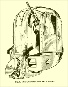
…” This unique spiral scanning system was placed into a Perspex dome and mounted at the base of the turret as shown in fig. 1. It rotates in azimuth with the guns when the turret is turned. The scanner is connected to the gun elevating mechanism by a parallel linkage so that it follows the gun movement in elevation. The aerial is a small dipole mounted near the focal point of a 40.64-centimetre parabolic reflector.
The dipole is mounted eccentrically and is spun by an electric motor at 2,000 revolutions per second. This causes the axis of the beam to follow a conical scan with a vertical angle of 11 degrees. The aerial is fed from a 9.1 cm. magnetron transmitter through a coaxial cable, and half-microsecond pulses are radiated at a pulse rate frequency of 660 per second.
The beam is about 17 degrees wide at half-amplitude and one might therefore expect to be able to pick up an aircraft approximately within a 30-degree cone. In fact, the sensitivity is sufficient to enable aircraft to be picked up over a 35-deg. cone in most cases. Aircraft can be detected by the rear gunner over most of the rear hemisphere, since the axis of the beam can be scanned over± 85 deg. in azimuth and ± 45 deg. in elevation. This form of search involves manual control of the turret and is tedious, but it need not be normally employed since most aircraft fitted with H2S are also fitted with Fishpond, which has a coverage over the whole of the lower hemisphere
The maximum range of AGLT is artificially restricted to 4,000 feet. This range was chosen in order to limit the number of casual contacts from friendly bombers and to eliminate ground returns. The minimum range of the system is about 500 feet
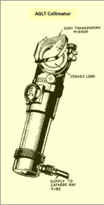
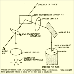
Usually, the operator of a radar equipment looks directly at a cathode ray tube, but in this case the image of the spot is projected into the gunsight through an optical system containing mirrors and a convex lens. The direction of the enemy aircraft was indicated by the movement of a bright spot on a cathode ray tube. This form of display is sometimes known as a spot indicator. The displacement of a bright green spot from the centre point of the tube gives a measure of the bearing and elevation of the attacking aircraft. The display unit therefore consists of a cathode ray tube with an attached optical system.
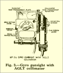
The complete unit, which is called the collimator, is shown in fig. 2.The collimator is mounted on the right-hand side of the gunsight with the axis of the tube vertical and the screen facing upwards. Fig. 3 is a sketch of the sight with the collimator attached.
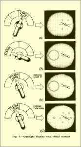
The Mk. II C gyro gunsight is a reflector sight. The aiming point is seen by the gunner as a bright spot in the centre of a circle of diamonds as shown in fig. 4(a). The aiming point which is produced by reflection is called the graticule.
The Mk. II C gunsight is, a predictor sight, the graticule moving about under the influence of a gyro and an electromagnetic system. This is superior to a fixed sight, where the gunner must allow for the effect of gravity on the bullet and the movement of a target by aiming in front and slightly above the target. In firing from a moving aircraft, other allowances must be made. The Mk. II C gunsight allowance is computed electrically and the graticule is automatically offset from the fixed aiming point by the correct amount This simplifies Gunlaying to a considerable extent.
For night firing, the image of the AGLT green spot is observed in place of the target aircraft, and the guns are moved so that the green spot is central in the graticule, see fig. 4. In this way the gunner is able to keep his gunsight graticule lined up on an invisible target by regarding the image of the cathode ray tube spot as the target. Obviously when firing during the day, the gunner simply moves the guns to keep the enemy aircraft encircled by the graticule with the central aiming point superimposed on the target.
When operating, either during the day or at night, range is automatically fed into the gunsight computer from the RADAR return signal and AGLT receiver. The gunner therefore has no ranging difficulties when the sight is used in conjunction with radar equipment. It is convenient, however, for him to be aware of the approximate range of a target without having to look away from the gunsight, so that he may know when to open fire. In visual firing, the appearance of the target is sufficient for this purpose.
For blind firing, the difficulty is overcome by making the spot grow wings to give the gunner an approximate idea of range. The length of the wings is about equal to the projection in the gunsight of an aircraft with a wing-span of 120 ft. The wings, however, do not grow at a steady rate that would be expected for an approaching aircraft. They lengthen gradually at first and then rapidly at about 500 yards, which is a suitable range for opening fire….’’ 4
Operation
The following is an extract from paragraph 12 to 14 of the Introductory Survey of Radar Part II Air, Publication 1093D 1946
12. ‘’…The navigator is responsible for switching on the H2S and AGLT equipment. The PEDAL/RADAR Switch in the turret is placed in the RADAR position to ensure that automatic range information is fed to the gunsight computer. The AGLT controls which are available to the operator are three in number, and are situated on the gunner’s control unit, fig. 5. The intensity of the cathode ray tube spot may be varied by means of a brightness control. A similar control is provided on the gunsight for adjusting the intensity of the graticule. The gunsight selector switch is turned to the GYRO-DAY position. Height and airspeed are set in, and these require resetting should an appreciable change take place. Should the gunner wish to check the tuning of the AGLT receiver a switch on the control unit is rotated to the TUNE position. The cathode ray tube spot is then replaced by a horizontal range time base which is reflected into the sight. The guns are depressed, and a tuning knob adjusted until the ground returns appear at maximum amplitude. Range time base reflected into gunsight for tuning on ground return.
13. When the receiver is tuned as described, the switch is returned to NORMAL and the spot reappears. It should be coincident with the centre of the graticule when the turret is stationary and there is no target within range. If attack is probable the gunner searches by moving the guns in azimuth and elevation in a regular manner. Usually, he may confine his attention to the region behind and above the aircraft because the Fishpond equipment gives warning of attack from below. Should the Fishpond operator observe an aircraft, he informs the gunner of the approximate direction of attack. If the range of the target is greater than 4,000 ft. the gunner will see no change in his gunsight, except that during movement of the turret and guns and for about a second afterwards, the graticule will appear to move in a direction opposite to the direction of motion of the guns and turret.
14. When the target comes within range of the AGLT equipment three things happen. The cathode ray tube spot starts to grow wings, and a chopped-up 1,500 cycle per second note is heard by all the crew on the intercommunication system. This note consists of pips at about two second intervals. In addition, the spot moves to a position where it is collinear with the target and the gunner’s eye. The gunner must now move the turret and guns so that the centre spot of the graticule follows as closely as possible the projection of the spot. By doing this he is feeding information into the gyro gunsight. As the fighter aircraft approaches, the wings continue to grow larger, and the pips heard in the intercommunication system grow more frequent, until at 500-ft. range the total wing-span extends over about 11 degrees, and the pips are occurring at a rate of about six a second…’’
The Range is also fed from the radar equipment to a range metre above the wireless operator’s position. As an additional aid to the gunner the wireless operator calls the ranges during the interception, and the pilot can judge when to start evasive action. If the gunner can see the enemy aircraft he changes over to visual firing. In order to remove the green spot from the cathode ray tube during visual firing, a SPOT CUT OFF switch is fitted between the turret-rate handles.
It is essential that a rapid and secure method must be deployed to enable the rear gunner to identify a friendly aircraft picked up on his beam. An Identification Friend or Foe (IFF) equipment called Liquid Lunch was being designed for this function. Another scheme which had been operationally employed used infra-red radiation. Here friendly aircraft are fitted with an infrared lamp in the nose. This is on continuously, but is invisible to the naked eye. A Type Z infra-red receiver, which deployed an infrared filter and a fluorescent screen, is mounted on the sight arch to the left of the gunsight. When the gunner wishes to determine the nature of the target picked up on his beam, he looks through the eyepiece of the Type Z telescope, and if he sees a green spot he knows that his target is friendly, but if he doesn’t see the light he knows that he has picked up an enemy target.
The Optical System of the Gunsight and Collimator
The following is an extract from paragraph. 18 and 19 of the Introductory Survey of Radar Part II, Air Publication 1093D 1946
18.”… Fig. 7 is a sketch of the optical system of the gunsight when used with AGLT. The target is observed through a transparent plate R1, which is inclined so that the reflection of the illuminated graticule can be seen. As already mentioned, the central point of the graticule is the gun aiming point, and the turret is operated to make the image of this spot coincide with the target. The illuminated graticule is itself situated at the focus of a convex lens LI, and, therefore, its image appears to be at a very distant point. There is then no error in sighting due to movement of the gunner’s eye. The collimator is fitted with two reflectors. The outer one, R2, is a transparent plate mounted obliquely in the line of sight, so that the image of the cathode ray tube spot may be observed. This image also appears at a distant point because the spot itself is at the focus of the collimator lens L2.
19. A selector switch is fitted in the turret and the graticule described above may be seen when the switch is rotated to the GYRO DAY position, (fig. 4(a)). When it is turned to the position marked FIXED, the graticule is no longer visible, but a bright ring with a cross at the centre takes its place, (fig. 4(b)). This is a second aiming point which will be called the fixed graticule to distinguish it from the moving or predictor graticule already described. The ring and cross is illuminated and projected into the sight through another lens placed on the left of L1. Both graticule images are visible if the switch is rotated to the FIXED AND GYRO position (fig. 4(c)). The fixed graticule is in fact seen by the left eye only, and the moving graticule by the right eye, but this is not confusing if the target is some distance away as in actual combat. The fixed graticule indicates the direction in which the guns are pointing, and if it is used in air firing the gunner must estimate an allowance and place the graticule ahead of the target as shown in fig. 4(d). But when the computer is working and the guns are being laid, the moving graticule is displaced from the fixed one, and automatically gives the correct allowance, so that the gunner simply keeps the six diamonds encircling the target as in fig. 4(a)…’’
It is sometimes useful for the gunner to see both graticules as he is then aware of the magnitude of the allowance and can judge when fire is likely to be effective. The computer has limitations, it can deal with allowances up to about 5 degrees, but beyond this angle there are greater errors in prediction and firing is unlikely to be successful.
Arial Bombardment of London by Doodle Bugs (V1) from, June 1944
The British operation to counter the V1 flying bombs “Operation Diver”, used ground based Automatic Gunlaying (using, among others, the SCR-584 radar) and the proximity fuse, both played an important part.
The V1 rocket had a payload of half a ton of TNT, the first attack occurred seven days after D Day, on 13 June 1944.
The proximity fuse project was started by civilian researchers at the Telecommunications Research Establishment (TRE), Worth Matravers, Dorset and led by Samuel C. Curran 5.
However, it took collaboration between the United States, Great Britain and Canada to complete and manufacture sufficient numbers required. The design was developed by USA Section T, led by physicist Merle A. Tuve, at The Johns Hopkins University Applied Physics Lab in Maryland in the U.S. The device determines when a shell, rocket or bomb explodes is called the fuse and is in the tip of the weapon. At the start of the war there were only direct contact fuses, which worked when there was a direct hit.
During the early German air raids on Britain, an anti-aircraft gunner reported that shooting down an aircraft in the night sky was ‘akin to hitting a fly in a darkened room with a peashooter’. A conservative estimate suggested it took 1,000 shells to bring down an aircraft. Variable time fuses halved this. They triggered a timer when the shell was fired, which allowed gunners to explode the weapons at a specific altitude.
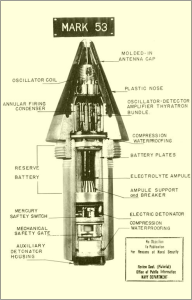
Curran and his team from TRE realised that what was needed was a way for the shells to sense the aircraft and detonate when they were close enough. The plan was to insert a tiny RADAR transmitter in the fuse that would emit a constant radio signal. This would reflect off any aircraft that came in range. The reflected radio waves would be picked up by the body of the fuse, which also served as the antenna.
The fuse used constructive and destructive interference to detect its target. The design had four or five thermionic valves. One was an oscillator connected to an antenna; it functioned as both a transmitter and receiver, known as autodyne detector. If the target was far away, little of the oscillator’s transmitted energy would be reflected to the fuse. When nearby, it would reflect a significant portion of the transmitter signal.
Therefore, the amplitude of the reflected signal corresponded to the closeness of the target. This reflected signal would affect the oscillator’s plate current and enable detection.
However, when the reflected signal was in phase, the oscillator amplitude would increase and the oscillator’s plate current would also increase, but when the reflected signal was out of phase, the combined radio signal amplitude would decrease and the plate current would decrease.
This issue was resolved by taking advantage of the change in frequency of the reflected signal. The distance between the fuse and the target was not constant but rather constantly changing due to the high speed of the shell fuse and any motion of the target. When the distance between the shell fuse and the target changed rapidly, then the phase relationship also changed rapidly. The signals were in-phase one instant and out-of-phase a few hundred microseconds later. The result was a mix of two signals of different frequencies, this results in a “beat”or heterodyne beat frequency which corresponded to the velocity difference. Consequently, a low frequency signal, corresponding to the frequency difference between the oscillator and the received signal, developed at the oscillator’s plate terminal. Two of the four thermionic valves in the variable time fuse were used to detect, filter, and amplify this low frequency signal. Note here that the amplitude of this low frequency ‘beat’ signal corresponds to the amplitude of the signal reflected from the target. If the amplified beat frequency signal’s amplitude was large enough, indicating a nearby object, then it triggered the fourth thermionic valve a gas-filled thyratron.
When triggered, the thyratron conducted a large current that set off the electrical detonator 7.6 metre to 22.8 metres from the target and showering it with shrapnel.
There were serious problems to overcome. The acceleration forces experienced on firing the shells were in the order of 20,000 G-force. To keep the projectile on a stable course, the shells were fired along a rifle barrel that imparted a spin of up to 30,000 revs per minute.
These large centrifugal forces would not be a problem for the solid-state transistors of today, but back then all they had were large, delicate glass thermionic valves.
The scientists at Johns Hopkins University Applied Physics Lab, Maryland U.S.A. proposed a solution to the problem – a fuse ten times smaller, containing a rugged thermionic valve developed from versions fitted to hearing-aid amplifiers 6.
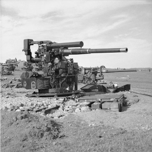
3.7-inch anti-aircraft guns, Hastings, 28 July 1944. Public Domain Creative Commons Compatible License (CC BY-SA 3.0 GFDL)
Both of these had been requested by Anti Aircraft Command and arrived in numbers, starting in June 1944, just as the guns reached their free-firing positions on the south eastern coast of England. Seventeen per cent of all flying bombs entering the coastal ‘gun belt’ were destroyed by guns in the first week on the coast. This rose to 60 per cent by 23 August and 74 per cent in the last week of the month, when on one extraordinary day 82 per cent were shot down. The rate increased from one V-1 for every 2,500 shells fired to one for every hundred.
After the war, the radar was adapted for use in the AN/MPQ-12, and AN/MPM-38 systems, a US Army field artillery missile system (MGM-5 Corporal). A modified version was also used to control and beacon-track (using an onboard transponder) the CORONA spy satellite.
In 1953, the SCR-584-Mod II was used for tracking the Redstone rocket, its range extended to 740 km by the use of an onboard transceiver.
Despite using vacuum tubes and being powered by an analogue computer, some specimens of the SCR-584 are still operational today. In 1995 the first Doppler On Wheels (DOW) radar adapted the MP-61 pedestal from an SCR-584 for use in a mobile weather radar. Using this pedestal, the DOWs created the first maps of tornado winds, discovered hurricane boundary layer rolls, and pioneered many other observational studies 7
References
- Penley J. Dean M.1979 Radar Museum Swanage The Purbeck Radar Museum Trust [Online] Available from: http://www.purbeckradar.org.uk/biography/bowen_eddie.htm[Accessed 9th Dec 2022]
- Ryan D 2022 Outreach Office MIT Lincoln Laboratory [Online] Available from: https://www.ll.mit.edu/news/lincoln-laboratory-commemorates-scr-584-historical-pioneer-radar-development
- Bennett S.1993 A History of Control Engineering: 1930-1955 [Online] Available from: https://en.m.wikipedia.org/wiki/SCR-584_radar
- Air Ministry 1946 (Declassified 1977) Introductory Survey of Radar Part II Air Publication 1093D Vol. 1
- Penley J. Dean M.1979 Radar Museum Swanage The Purbeck Radar Museum Trust [Online] Available from: http://www.purbeckradar.org.uk/biography/curran_sam.htm
- Bureau of Ordnance 1946 VT Fuzes For Projectiles and Spin-Stabilized Rockets, Ordnance Pamphlet, vol. OP 1480 U. S. Navy Bureau of Ordnance [Online] Available from: https://en.wikipedia.org/wiki/Proximity_fuze
- McMurran W.R 1973 The Evolution of Electronic Tracking NASA0TM-X-70077 [Online] Available from: https://en.wikipedia.org/wiki/SCR-584_radar
