TRE 1940
In May 1940, the Air Ministry posted personnel located at Dundee to St. Aldhelm’s Head, Worth Matravers, a windswept location four miles west of Swanage. The site, named Air Ministry Research Establishment (AMRE) Worth, had been operational since 1939.
The Air Ministry Research Establishment (AMRE) to TRE Name Change
In 1919, the Air Ministry formally took control of supply, design and inspection of all aircraft (aeroplanes and airships) from the Ministry of Munitions. This helped put the existence of Air Ministry on a firmer footing. Throughout 1919 Winston Churchill persistently supported an independent air force. He presented the White Paper, largely written by Sir Hugh Trenchard, on the future of the RAF on 12 December 1919. It was this White Paper that was to be the effective charter for the RAF and Air Ministry in subsequent years.
On the 10th May 1940, Winston Churchill became Prime Minister, from his personal experience of the Ministry of Munitions in the First World War, he considered that the Air Ministry should devote its energies to fighting the war and that a separate ministry should have the job of providing the hardware. This new organisation was called the Ministry of Aircraft Production (MAP) and it was to be led by Lord Beaverbrook.
The consequence of this decision was that the name Air Ministry Research Establishment, AMRE Worth would change to MAPRE Worth, this caused issues when introducing the site name over the telephone. This complaint went to Whitehall, London and within a month a solution was provided, the title should change to Telecommunications Research Establishment (TRE) in November 1940 33. This solution had two advantages: it would fool the enemy because Worth did not provide telecommunications and the abbreviation TRE flowed easily from the tongue, making telephone conversations easier.
The TRE 10 Centimetre Group
In May 1940, the Air Ministry posted personnel located at Dundee to St. Aldhelm’s Head, Worth Matravers, a windswept location four miles west of Swanage. The reason why this location was chosen was its terrain, it had a high, flat clifftop which was considered good for testing RADAR, then known as Range Detection Finding (RDF). They were some of the best scientist in the country with their support staff. One of their goals was to develop an Aircraft mounted RADAR, which would enable a bomber pilot to view on a display screen a target location image 39. It was established as the central research group for RAF applications of radar 33.
This required three elements a transmitter, an aerial and a receiver that catered for 3GHz, a 10cm wave length.
In June 1940, Hut C was allocated to the 10 Centimetre group, this was led by Dr H.W.B. Skinner from the Wills physical laboratory at Bristol, the group was composed of Dr Lovell, Dr Skinner, Dr Burcham, Mr Jimmy Atkinson, Mr A. G Ward, Mr A Chapman -Lovell’s assistant and Mr P. I. Dee. Dee was responsible for the transmitter valve known as a Klystron, suggested by Professor Mark Oliphant from the Birmingham University. Dr Lovell and Chapman were responsible for the transmitter and receiver aerial and Ward the recieved signal detector.
A Swanage local had commented “Haven’t you got a lot of doctors up at Worth?” thinking they were all Medical Doctors.
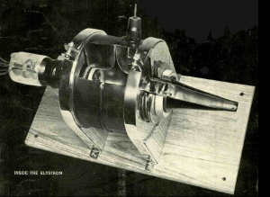
Klystron
The Klystron was huge, it was demountable from the framework and continuously evacuated, this required vacuum diffusion pumps and motor driven backing pumps; it was water cooled using a cold-water cistern. It had a large oil filled transformer and huge capacitors to provide the operational 20,000 volt. When the team managed to get it operational it only lasted 10 minutes. The next issue was to get the intermittent power to the Transmission Aerial. The cables available in 1940 were ineffective at that frequency so an alternate was to use two inch diameter zinc plated piping. This was provided by the local store who kept a supply of sanitation pipes generally used on the site chemical toilets, known as an Elsan chemical toilet kit. About three kits were collected to make the 12 feet connection between the Klystron output and the test neon lamp.
Aerial
While Dee was struggling to get power from the Klystron Lovell and Chapman were struggling to design a suitable aerial. There were no departure from established aerial practice when designing the Radiator, a dipole and reflector, a miniature version of the old “H” deployed on the 405 lined television system. Care had to be taken when designing the line connection to the aerial element. The two men spent most of the time outside testing different models of aerials until the optimum was found.
Receiver
A Canadian A.G. Ward was delegated the task of designing the 10cm receiver, he considered it a standing start, since there were no thermionic valves capable of working normally at this frequency, due to transit times in valves and another suitable detector was needed. Various valves were tried and the most promising was a BODE diode costing £1,000 which was lent to Ward by Standard Telephones and Cables. After an initial experiment the valve blew up, the cost was marked down to enemy action. It was then decided that a crystal detector was required. This was constructed by Skinner because he had the skill and experience of glass blowing.
The device consisted of a chip of silicon crystal bonded to a wire and the “cats whisker” a few coils of tungsten wire forming a spring. The two parts were enclosed into a glass tube with the “cats whisker” in contact with the crystal, forming a diode –a device that only conducts electricity in one direction.
This design was developed for production by the British Thompson Houston Company (BTH). Here they replaced the glass with a ceramic tube and installed metal end caps to facilitate mechanical assemble. The high frequency output was mixed with a lower frequency from Ward’s local oscillator, providing an output that could be amplified, creating the first centimetre mixer.
The standard practice in radio sets since the 1930’s, but not at this frequency!
During July 1940, there were only sporadic raids by a small number of enemy aircraft, the TRE personnel, witnessed the Portland naval base raid and attacks on shipping in the channel, but this all changed in August. Then the Battle of Britain started, from the site at Worth you would often hear a load humming noise from an armada of over 100 bombers, composed of Heinkels, Junkers and Dorniers supported by Messerschmitt 109 fighters. This armada appeared to be heading directly to RAF Worth, but before they crossed the coastline they were confronted by our Spitfire and Hurricane fighter planes. The Germans lost a lot of planes and later switched to night-time bombing, where the inhabitants of London and our large cities suffered.
In August 1940, there were no air raid shelters for personnel, they would hide behind dry stone walls under blackthorn bushes, there were no casualties, but a very near miss. This happened when a bullet fell from the sky, went through a shed roof and buried itself in the concrete not far from a staff member. This was the case for 18 months, then a lone hit and run raid from an enemy aircraft occurred. It swept in low over the sea, released its bombs and fired its cannons at the site. The bombs landed outside of the perimeter fence, destroying the RAF cookhouse and caused some casualties 39.
Requisition Schools
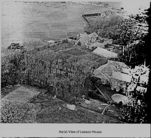
The Battle of Britain was reaching its peak and A.P. Rowe, the Superintendent of Worth TRE, was getting concerned about the safety of his precious staff and the time being lost in the air-raid shelters. To remedy this he requisitioned Leeson House a boy’s preparatory school, located two miles away near Swanage.
All staff at Worth who did not need the aerial tower facilities at Worth were moved there. The 10 Centimetre group was allocated the stone horse stables at the rear of the grounds, it needed a large conversion, but the end product provided the group with more space than the wooden hut at Worth. They moved down to Leeson in mid-September 1940, but even this location was not safe, because a month earlier at 2355 hrs on the 15th Aug 1940, three German bombs, were dropped in the grounds, luckily the buildings were still intact.
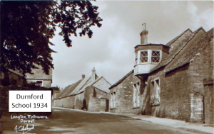
All groups located at Leeson House were creating new and original applications of the RADAR art and within the year the number of personnel working there had hit a crisis point and an additional building was required. Another prep school was requisitioned, half a mile west of Leeson, called Durnford School. Prior to the war, this School catered for boys between the ages of 7 to 14 years. The school curriculum was biased towards the entry requirements for the Dartmouth naval college. This was a much larger Manor house, built in the 18th century and originally owned by the Serrell family.
The school was in a poor state of repair and had multiple mezzanine floors and an uninviting swimming pool. One great advantage was that it had dining facilities that was often used by Leeson personnel. It was predominantly used by Administration staff under the leadership of A.P. Rowe the Superintendent of TRE Worth. Due to the success of the Magnetron the Leeson House staff numbers grew and another Prep school, Forres in Swanage, was requisitioned, this served as a RADAR school
The 10cm group continued improving their design, at this stage they were able to discern St Catherine’s Head on the Isle of Wight. All the elements were performing well except for one – the means of linking transmitter and receiver onto a common aerial with a single parabolic mirror, to enable the system to fit into the nose-cone on the twin engine aircraft.
It was almost a year before a satisfactory solution was found for the Transmit Receive cell, the Soft Sutton valve 39.
Magnetron Development
Early magnetrons had a dual-anode magnetron valve structure that had been used as high-frequency oscillators in university physics laboratories since the early 1920s. Though even at lower frequencies their efficiency was a miserable 5 to 10%.
The device was relatively simple – a central cathode, with a split anode around it, and a magnetic field arranged to be in line with the cathode.
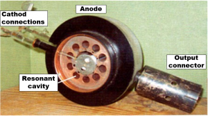
The photograph of a cavity magnetron shows what it looked like with the lid removed. It doesn’t show that it must be placed within the jaws of a huge magnet in order to work. Like its glass predecessor, this magnetron consists of a central cathode, surrounded by an anode, sealed in a vacuum and with an external magnetic field arranged to be in line with the cathode.
This device includes a brilliant and simple innovation. Instead of splitting the anode and connecting it to an external tuned circuit, the inventors (Randall and Boot, at Birmingham University) used lots of identical resonant-cavity tuned circuits and put them inside the anode. This allows the circulating electron cloud to interact directly with the tuned circuits.
Using the original magnetron Randall and Boot succeeded in getting the device to deliver 70 kW, but its efficiency was a miserable 10%.
Efforts to get more power out of was not successful. Then a colleague Prof. Sayers tried linking every other slot together, with bits of copper wire. Every alternate ‘capacitor’ is now effectively connected in parallel. The instantaneous voltage across all the parallel ‘capacitors’ has to be the same. These tuned circuits are compelled to operate in phase with each other. Alternate cavities must then be 180 degrees out-of-phase with their neighbours, or π mode which is 180 degrees.
The result was almost magical. Efficiency jumped to 50%, and 20 micro second pulsed power output could be increased five-fold to 50 kW 34.
The Sutton Valve
Receiver Modification
During transmission tests using two aerials, transmit and receive, they found that the receiver oscillator occasionally stopped and transmission ceased. This would have been particularly embarrassing if providing a public demonstration to the head of TRE, Watson-Watt. To resolve the issue the Admiralty Establishment at Bristol came to their aid with the delivery of a new valve, by two researchers Sutton and Tompson. The valve was hastily taken to a workshop connected to a power supply, a wire loop was inserted into a brass ring attached to a copper doughnut that was inside the glass seal and a flash light bulb was soldered to the wire. After some voltage adjustments the lamp lit and Sutton declared “3 Ghz or thereabouts”. It was the little brother of the Klystron but it relied on the electron optics within the tube as opposed to interaction of twin resonators 1.
To install a single aerial into an aircraft so that it acts as both a transmitter and receiver is not an easy task.
A solution was suggested by Arthur H. Cooke of the Clarendon Laboratory and production development was taken up by Skinner and Ward from TRE Worth. They took a Sutton tube and disconnected the electron gun and reflector, leaving just the cavity. This was filled with a dilute gas, initially helium or hydrogen, but eventually settling on a tiny amount of water vapour and argon.
When the transmission signal was seen on the input, the gas would rapidly ionize (helped by a heater coil or radium). The free electrons in the plasma presented an almost perfect impedance source, blocking the signal from flowing to the input. As soon as the transmission stopped, the gas de-ionized and the impedance disappeared very rapidly. The tiny echoes caused by reflections from the target, arriving microseconds later, were far too small to cause the ionization, and allowed the signal to reach the input 40.
The Radar Scanner
Centimetre RADAR emits a narrow beam that created issues when designing a suitable scanner. The solution adopted by the 10 Centimetre group was a spiral scanner, there were doubts about this design, as a contingency, Dee persuaded the General Electric Company (GEC) to make a helical version. In January 1941, both versions were operational and their operation parameters were compared whilst mounted on trailers at Leeson. After the tests, in February 1941 the original TRE version was chosen and mounted into a Blenheim N3522.
The spiral scanner was an extraordinary device. The 28 inch (0.8m) paraboloid spinning at 1000 rpm with an eccentricity varying at 30 degrees in one second produced a strange effect on an observer. The scanner was dynamically balanced and the vibration was insignificant. A glass of water standing on the framework would not make the water ripple.
H2S RADAR Navigation Development
In the autumn of 1941, the 10 centimetre group was divided into two, half under the leadership of Dr Skinner and Mr Jimmy Atkinson and the other half under P.I. Dee. Dee’s group was to develop H2S, a Terrain based Air to Surface Vessel (ASV) RADAR, but H2S was to operate at 10 centimetres as opposed to ASV’s 1.5 metre wavelength. It would be mounted in an aircraft where it would not be restricted in range. After the initial development, the system was mounted in a Blenheim bomber and flown over the Bristol Channel, this provided positive results, providing a clear image of the Severn estuary. After the test, Dee was summoned to a high powered progress meeting at the Air Ministry. The members were not impressed with his progress and asked him if he wanted help from them. He explained that he lacked manpower and required more working space. They asked him how much space; he replied a 60 foot hut. A few days later at Leeson House, a large lorry arrived loaded with wooden hut sections and a team of workmen and the 60 foot hut was erected next to their workshop, the old stables. When finished, a squad of RAF RADAR mechanics arrived led by a Flight Sergeant and they started work assembling the prototype units for flight trials.
H2S became operational in January 1943, it went from strength to strength, in all there were six versions from the initial Mk1 on S Band (9.8 centimetres) with X band (3 centimetres) variants Mk III and IV and a K band (1.25 centimetres). There was one drawback in using H2S, caused by the Germans having access to a Magnetron Valve that was removed from a shell damaged Bomber, they had reversed engineered it and developed a 10 centimetre receiver called Naxos which they installed into their night-fighters, enabling them to home in on H2S equipped planes. This caused a hazard to our bombers but it was partially resolved by adopting intermittent rather than continuous use of the H2S sets during an attack 39.
A.P. Rowe wrote:
It must be confessed that when R.A.F. personnel at Christchurch saw the first A.I. scanner system installed in an aircraft, doubts were cast on the sanity of the scientists. Before the system reached a speed of rotation greater than the eye could follow, it could be watched rotating in a curiously irregular fashion with the one apparent desire of escaping from the aircraft altogether. When however the system was found to do its job and to give less trouble than many devices of greater respectability, the R.A.F. personnel soon learnt to regard it as a normal piece of equipment. 39.


